frame assembling
frame assembling
Congratulations on the purchase of your COMMENCAL 365 frame. Here we offer some help so you can build it up and get out there!
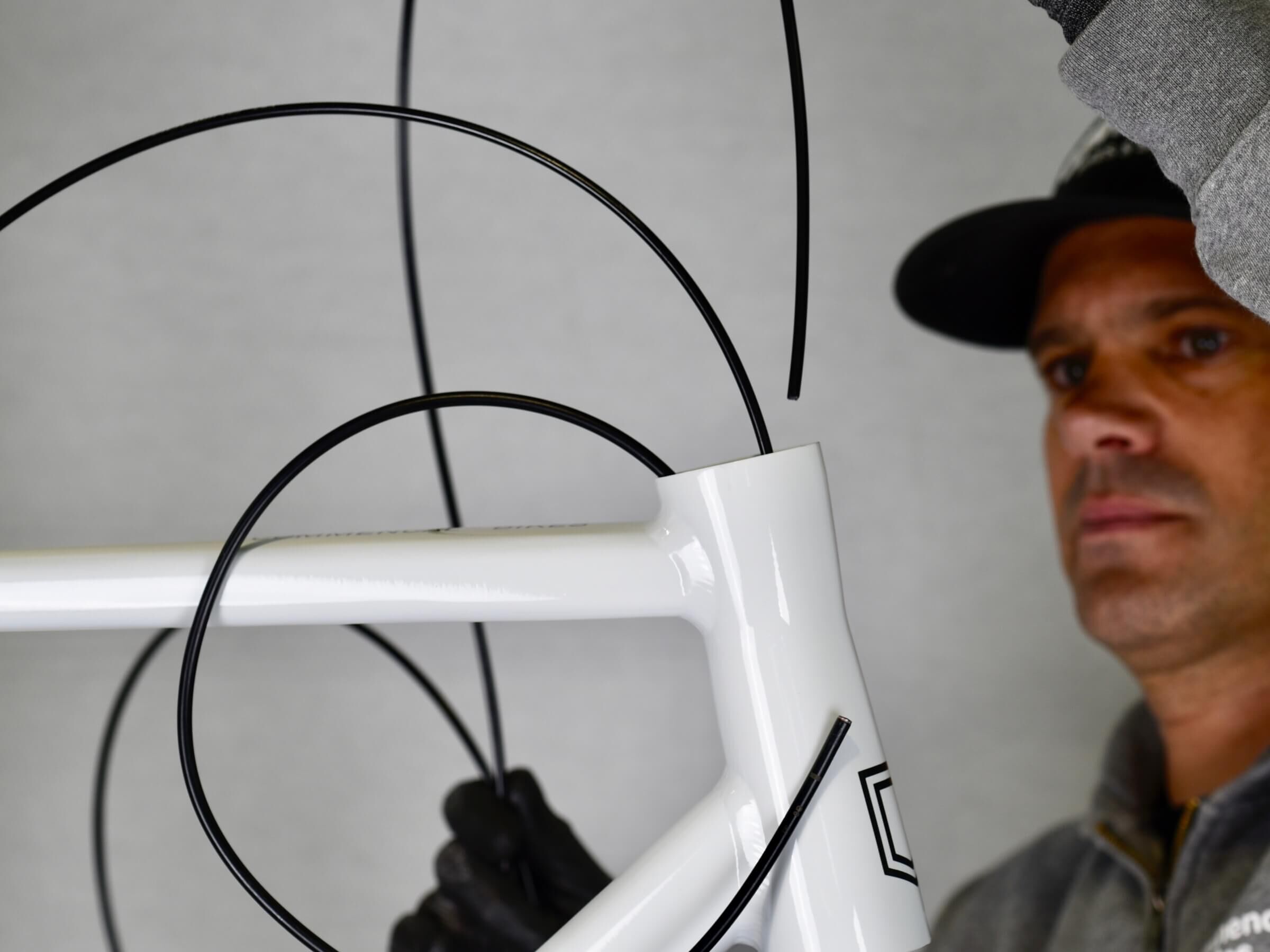
First step of the build is the internal hoses routing, fork and headset installation.
STEP 1
STEP 1
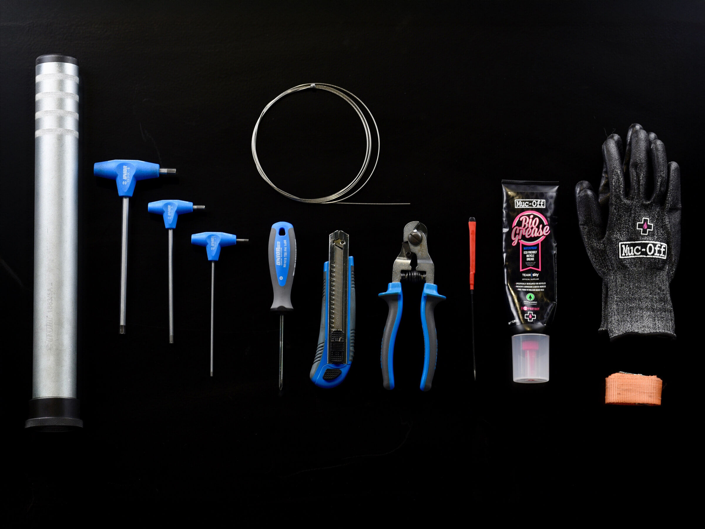
Prepare the necessary tools before you start :
- Allen keys set ( 2,5 / 4 / 8 )
- Philips screwdriver
- Cutters
- Protective gloves
- Torque wrench
- Assembly grease
- Pick
- Crown race setter
- Strap
STEP 2
STEP 2
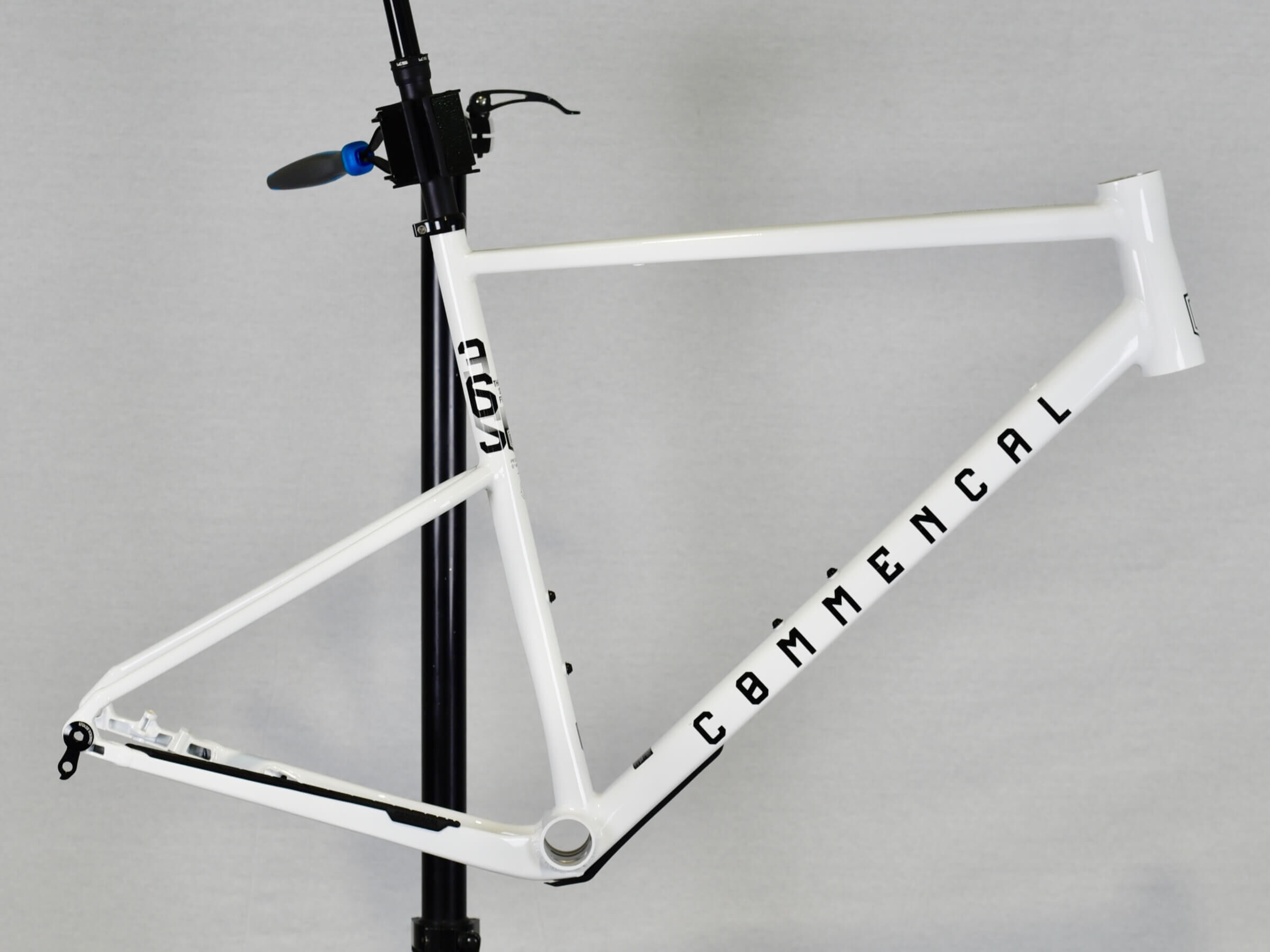
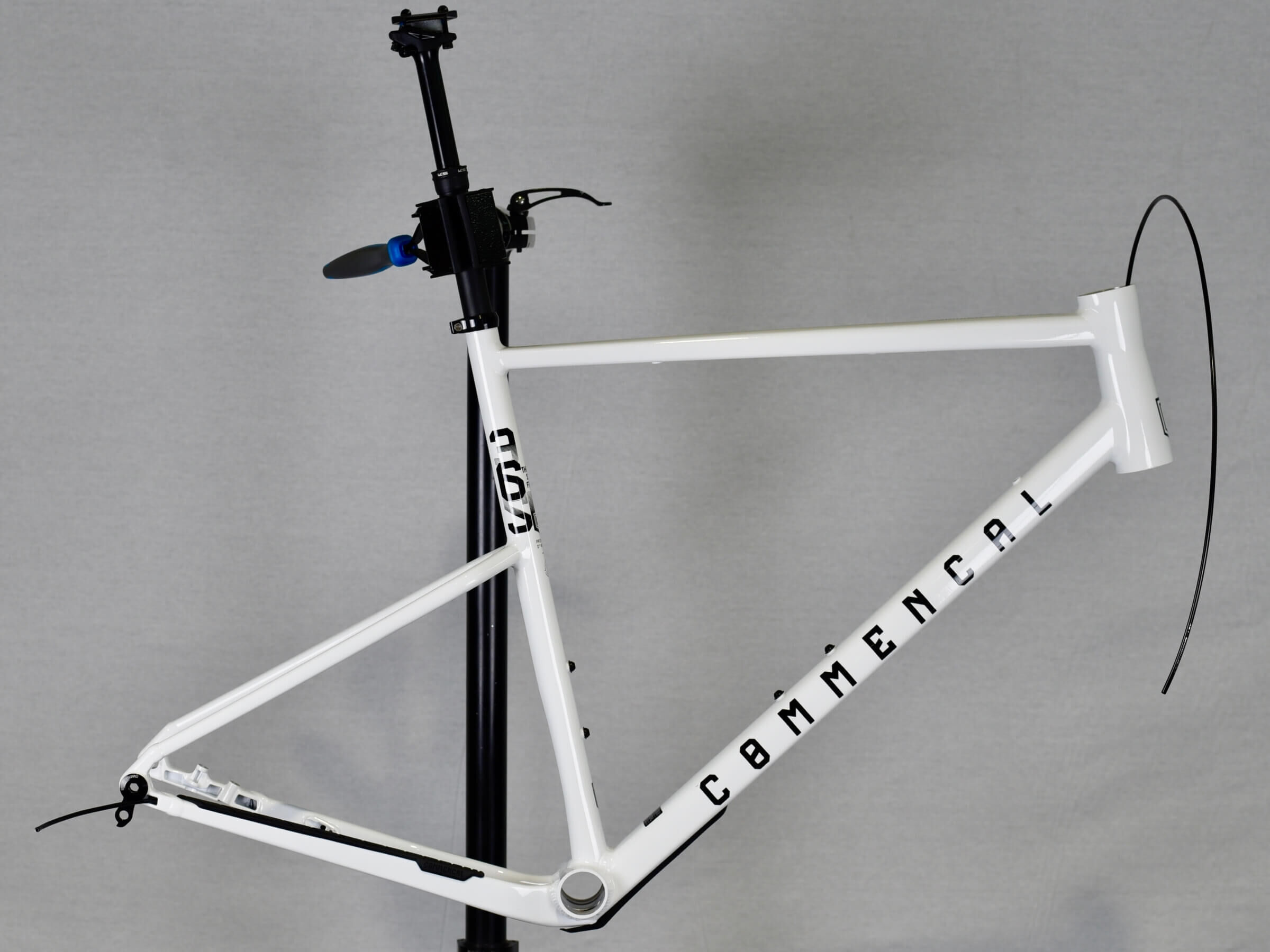
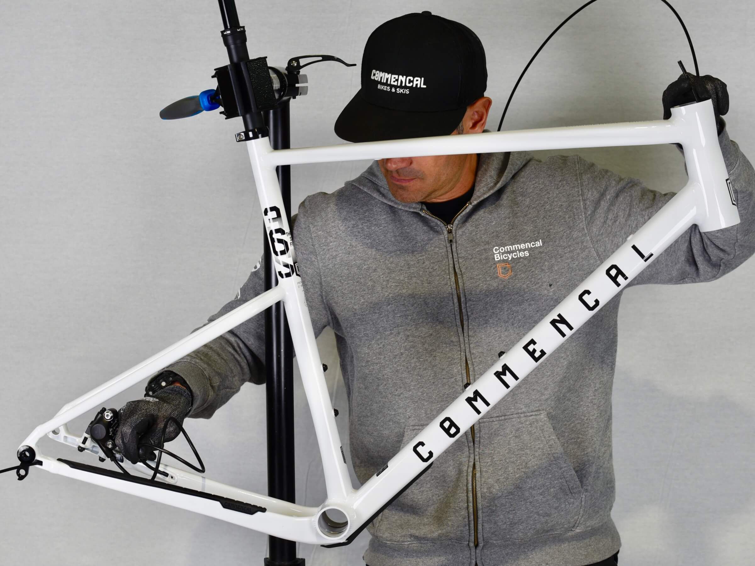
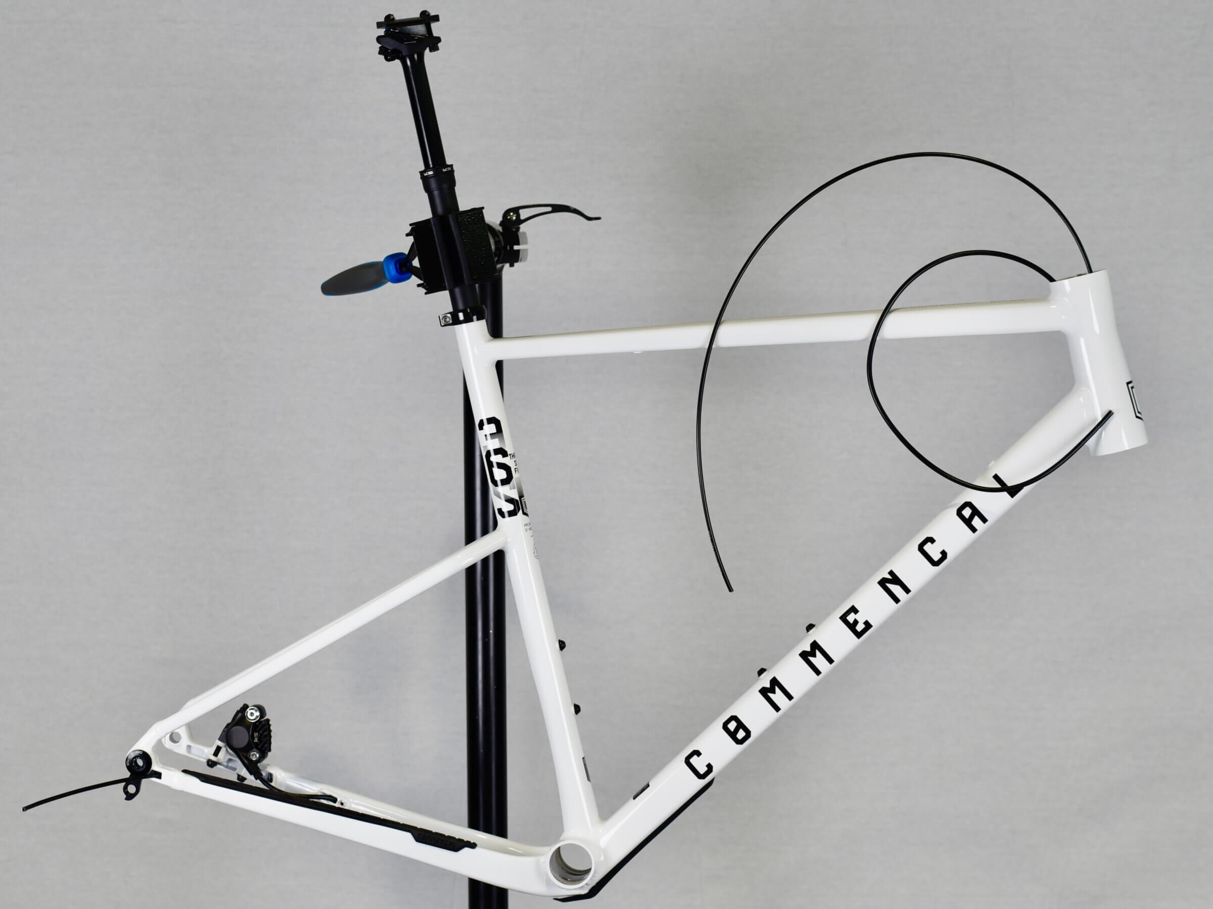
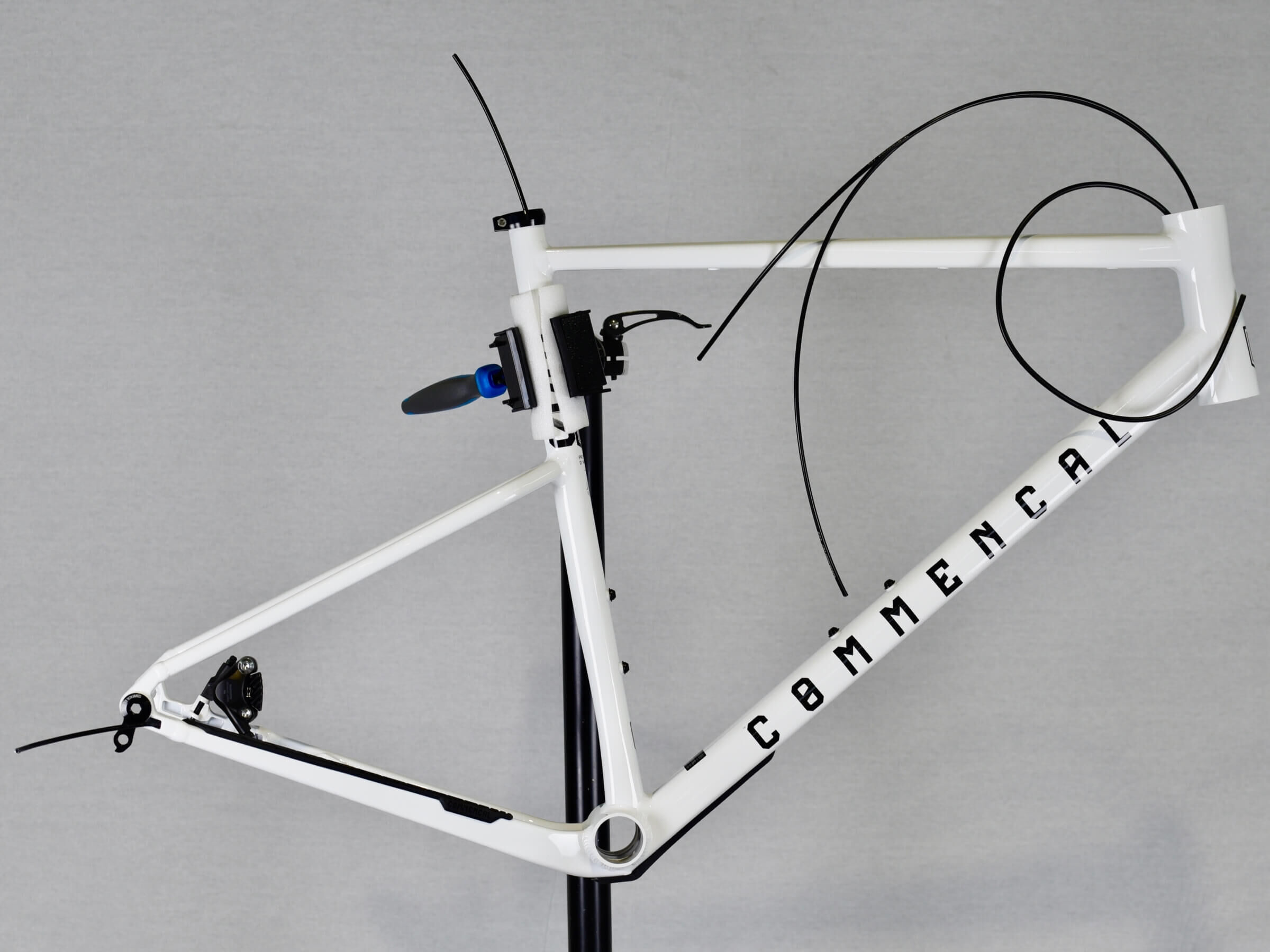
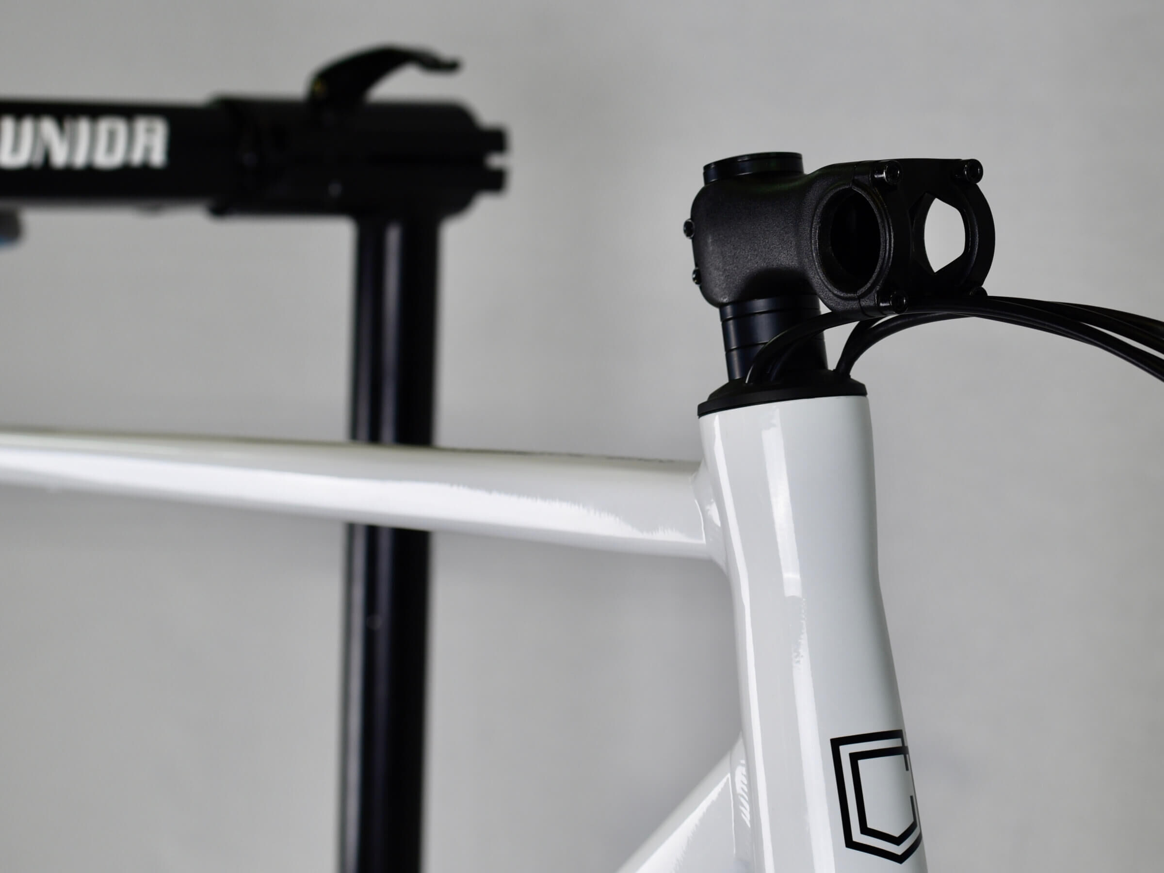
Install your 365 frame on a bike stand, with seat clamp and dropper post assembled.
STEP 3
STEP 3
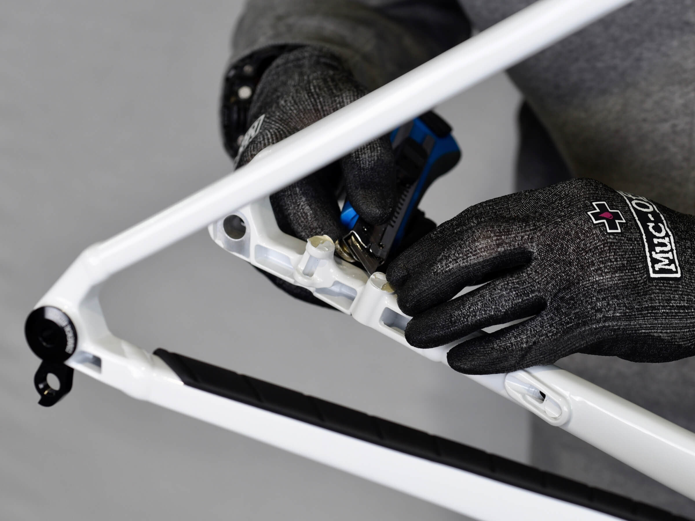
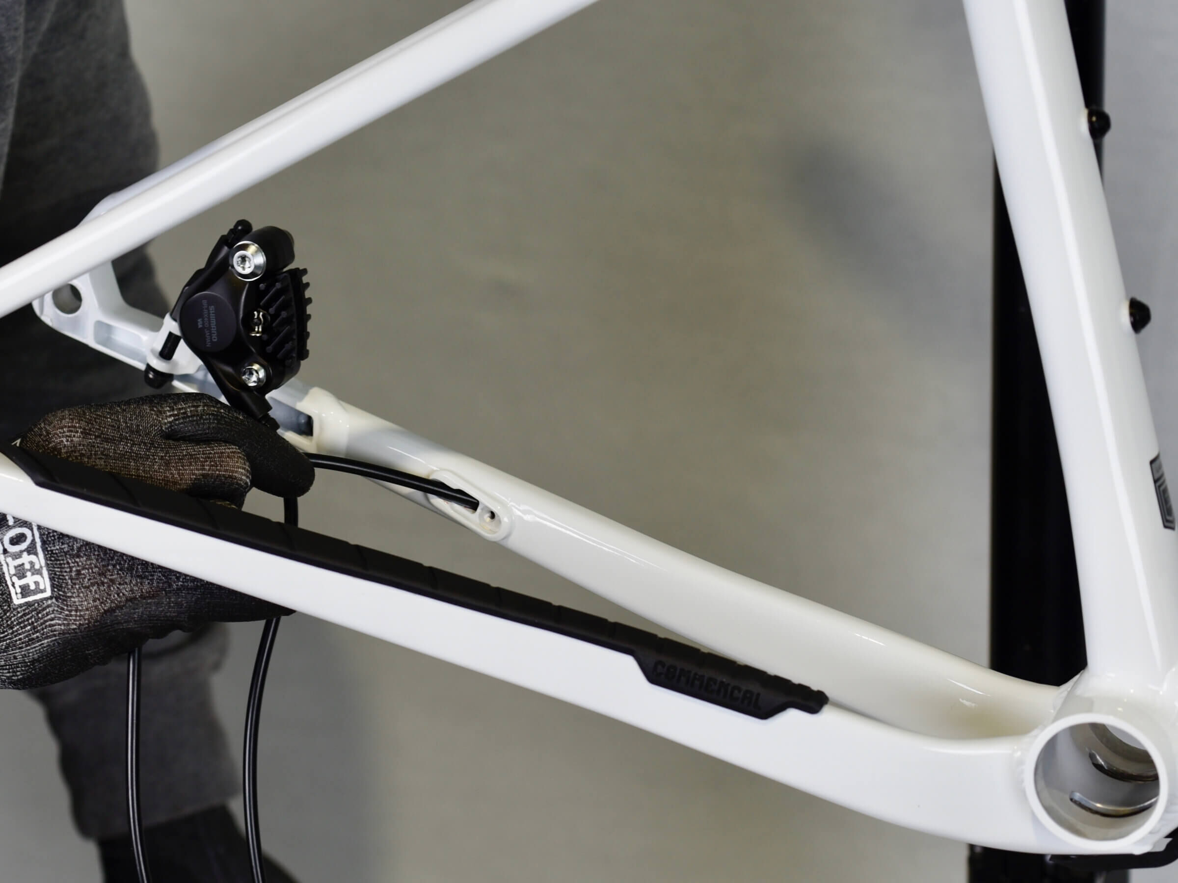
With the cutters, remove paint masks from brake mounts.
STEP 4
STEP 4
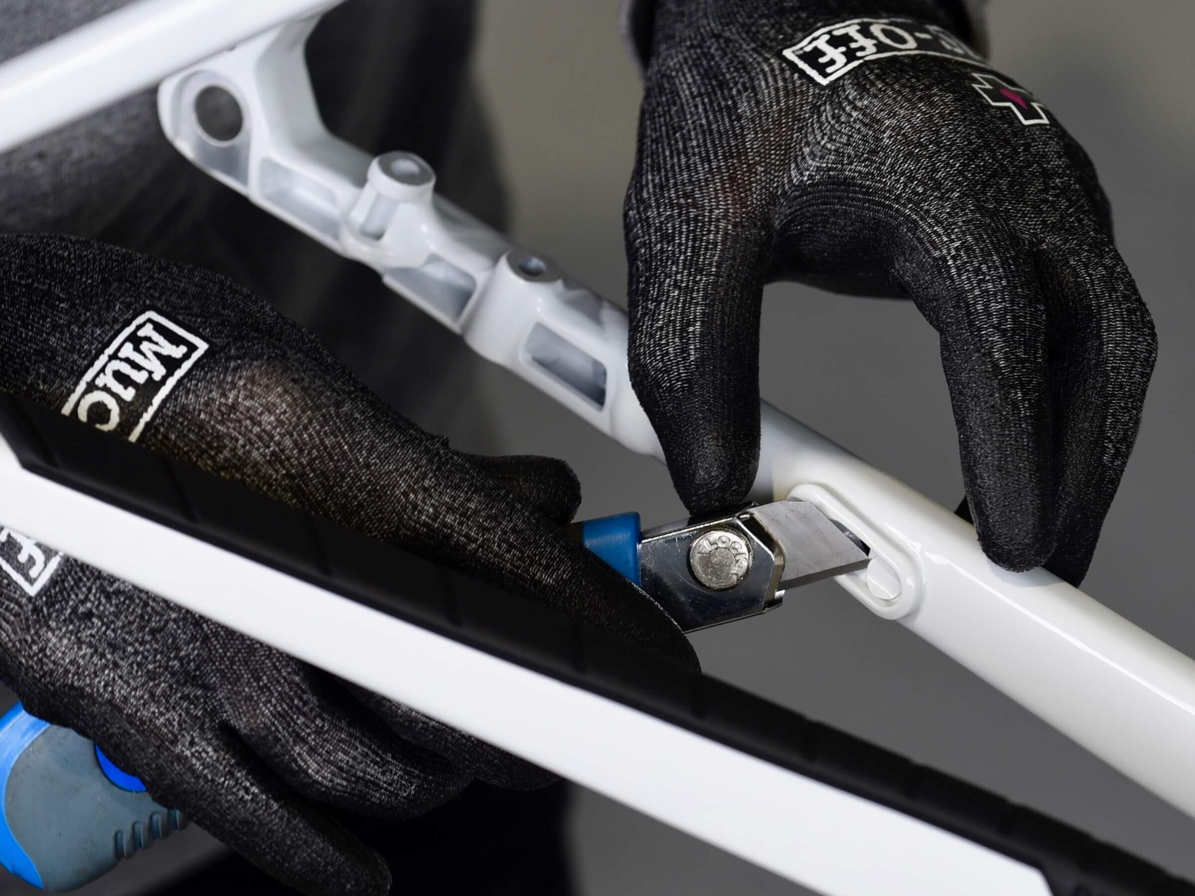
With the cutters, remove paint mask from chain stay routing hole.
STEP 5
STEP 5
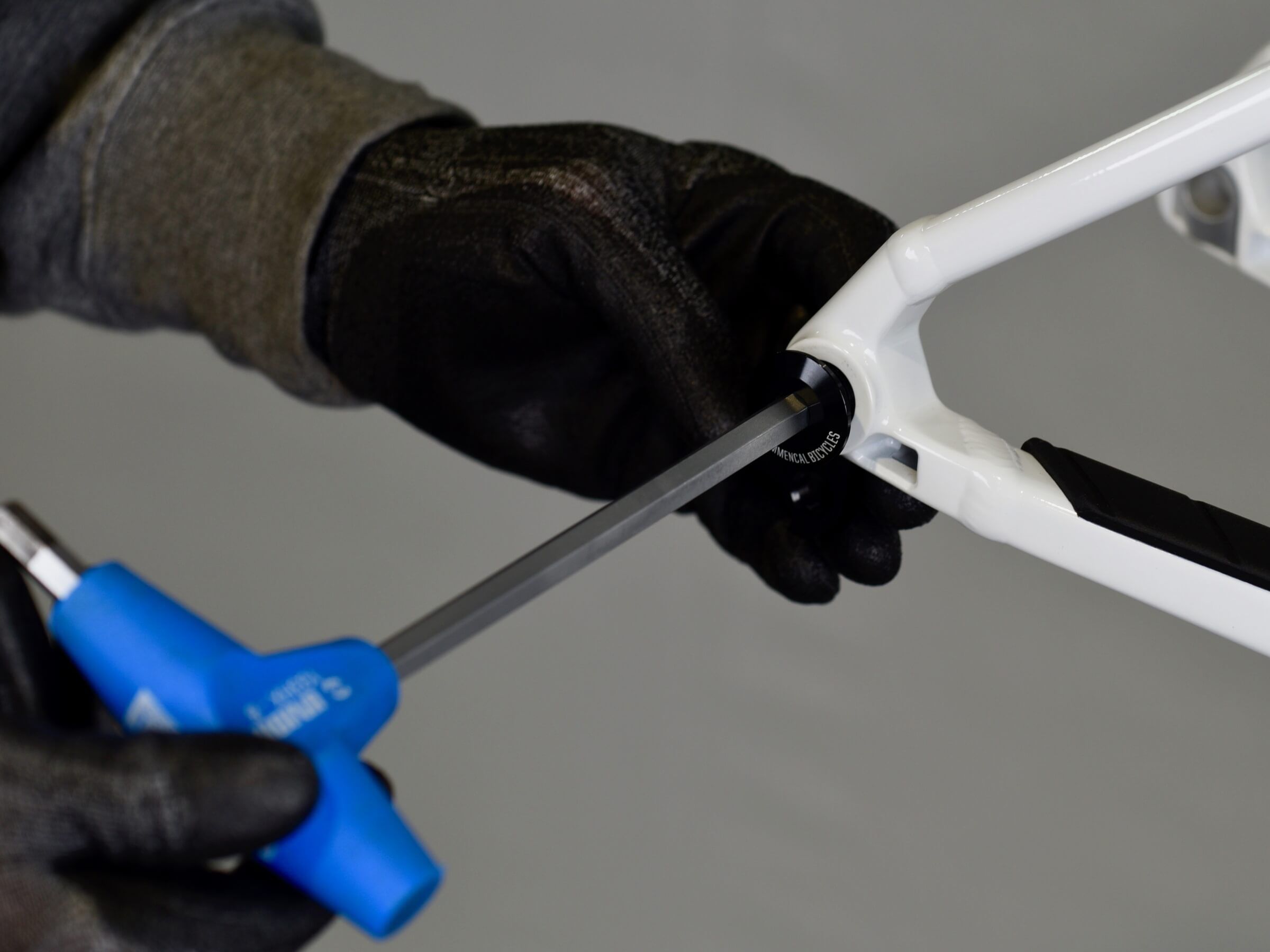
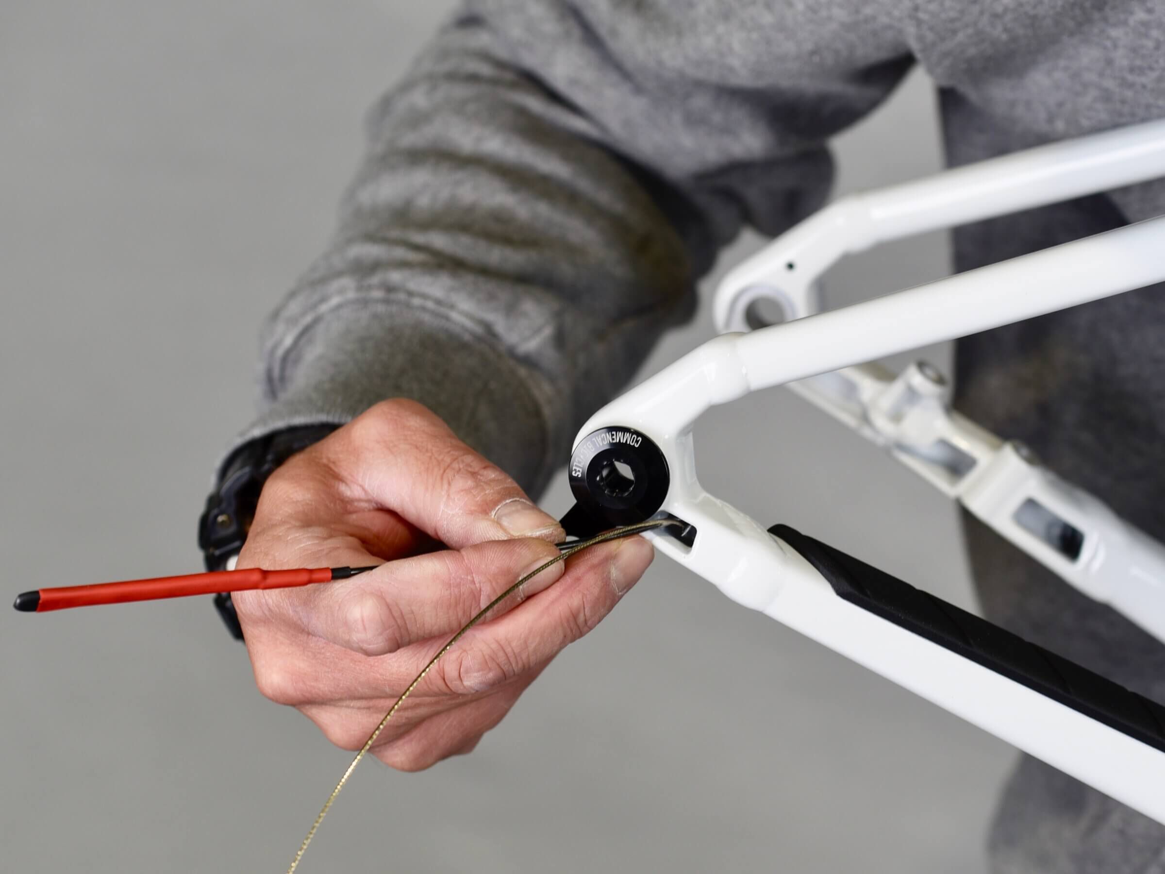
With a 8mm Allen key, remove the derailleur hanger bolt. The thread is inverted, so rotate the key anti clockwise to remove it.
STEP 6
STEP 6
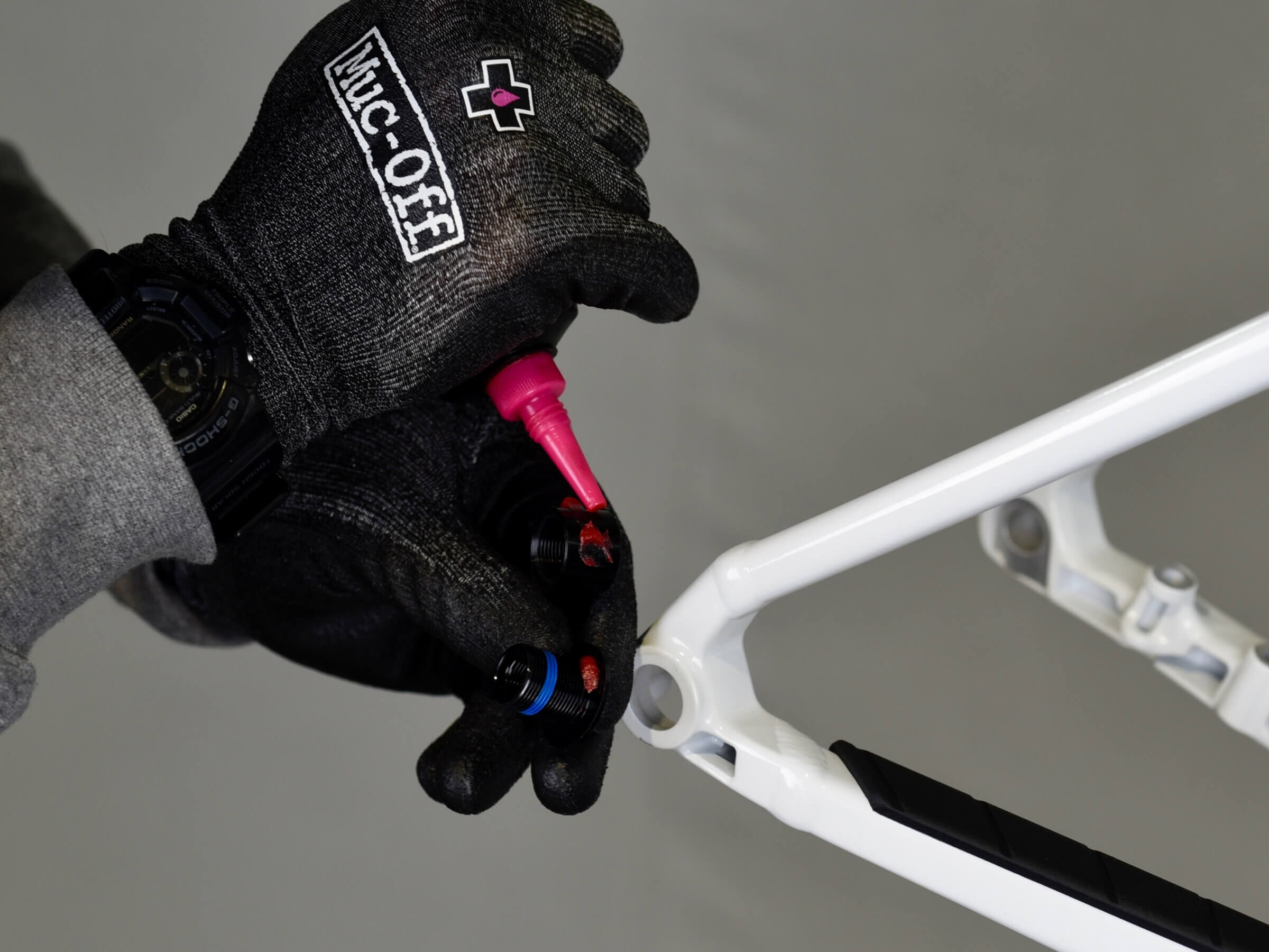
Grease the hanger at frame contact zone, to avoid any creaking noise.
STEP 7
STEP 7
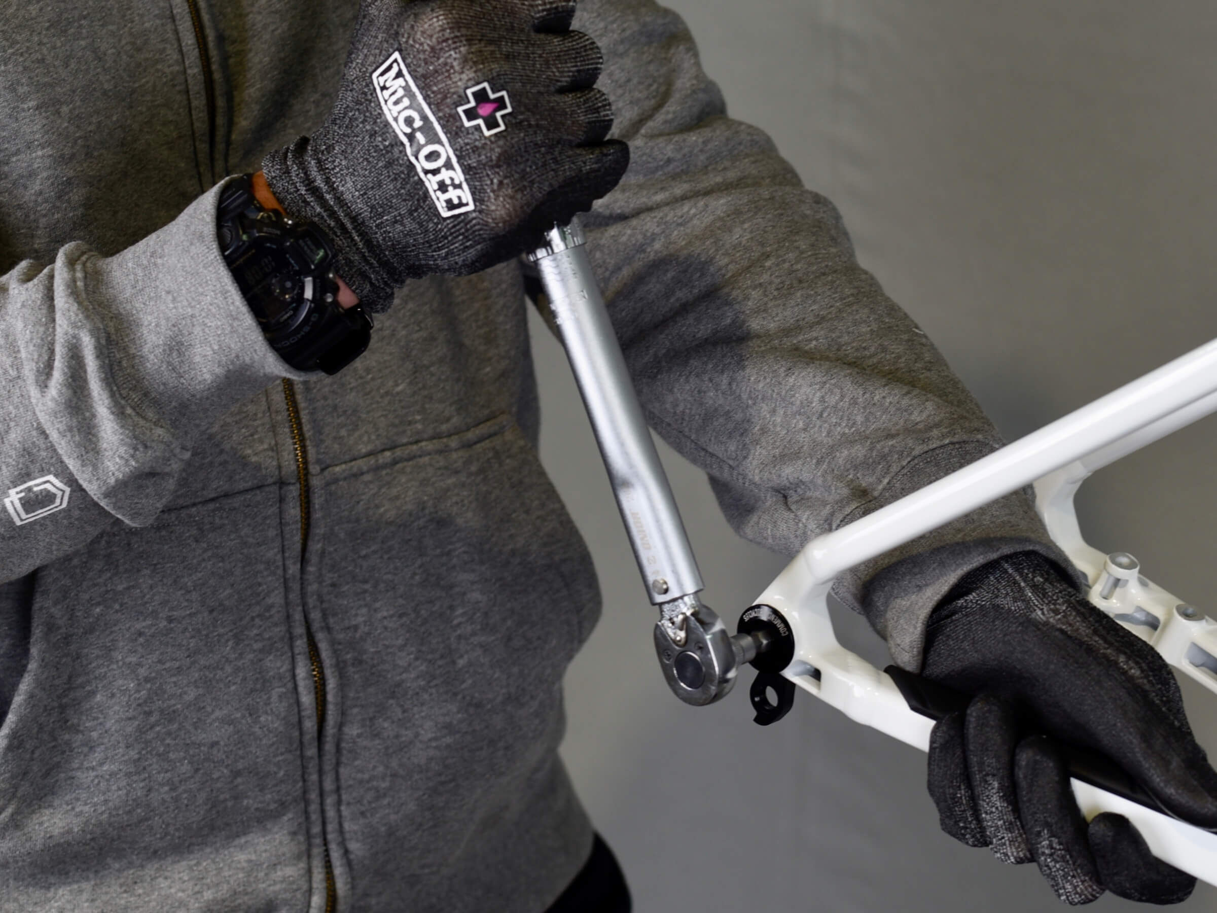
With dynamometer wrench, torque hanger bolt to 9N.m
If your dynamometer wrench cannot be switched, torque from the inside.
STEP 8
STEP 8
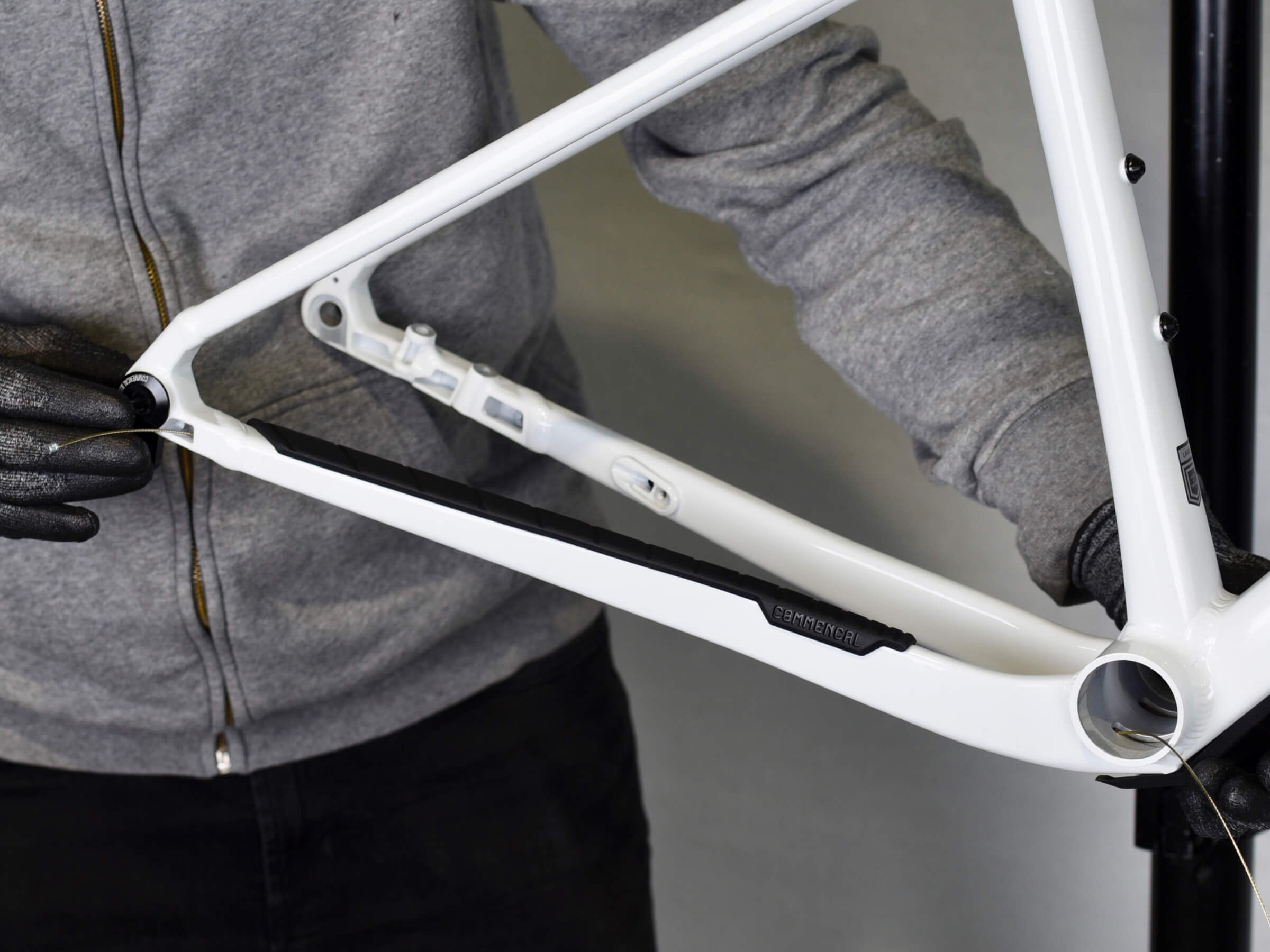
Next step is to route the derailleur housing inside the frame.
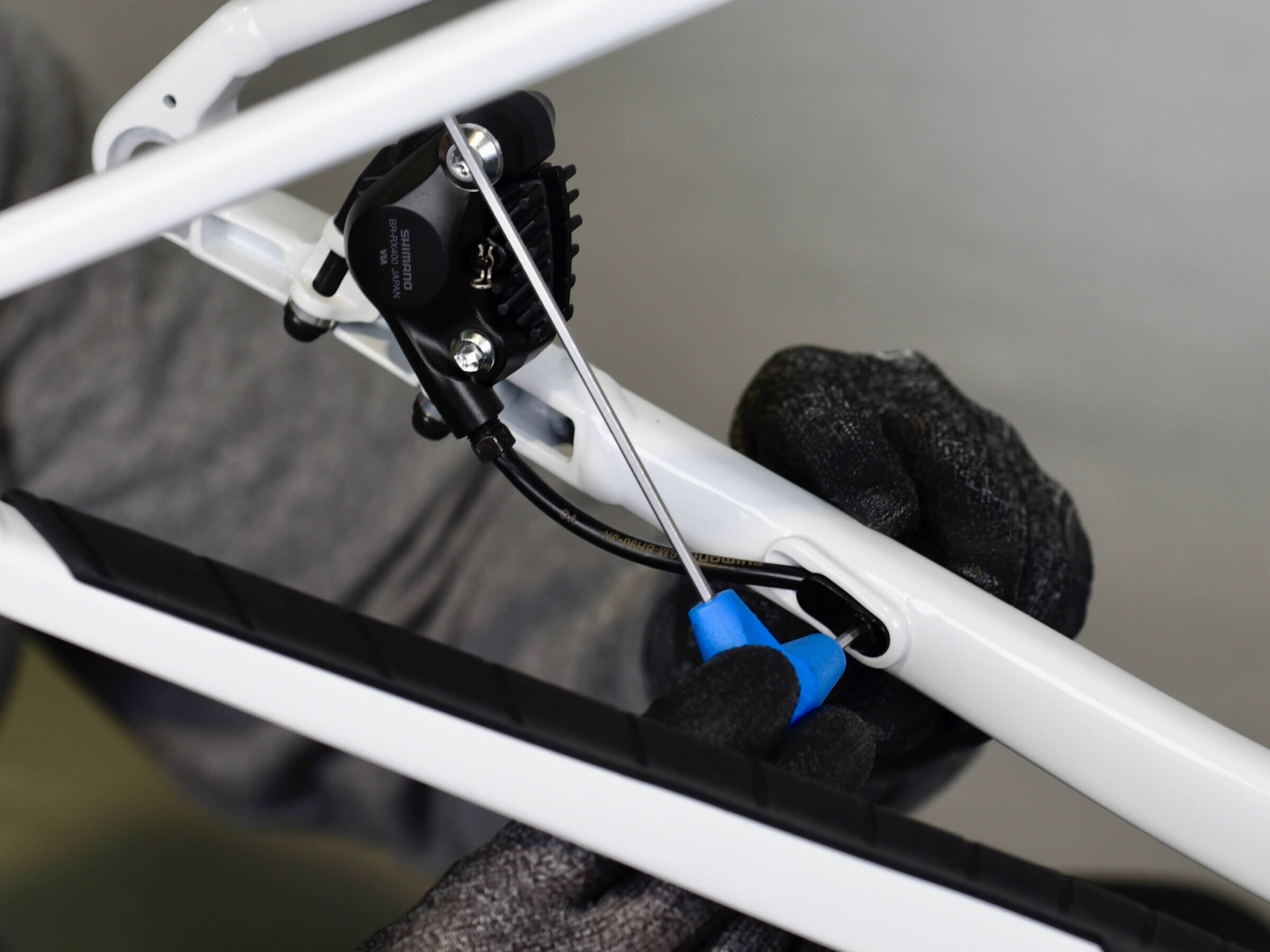
Use a brand new shifting cable, and route it in the right chain stay, from the bottom bracket to the back, head first.
STEP 9
STEP 9
The cable must get out of the chain stay by the hole next to hanger.
STEP 10
STEP 10
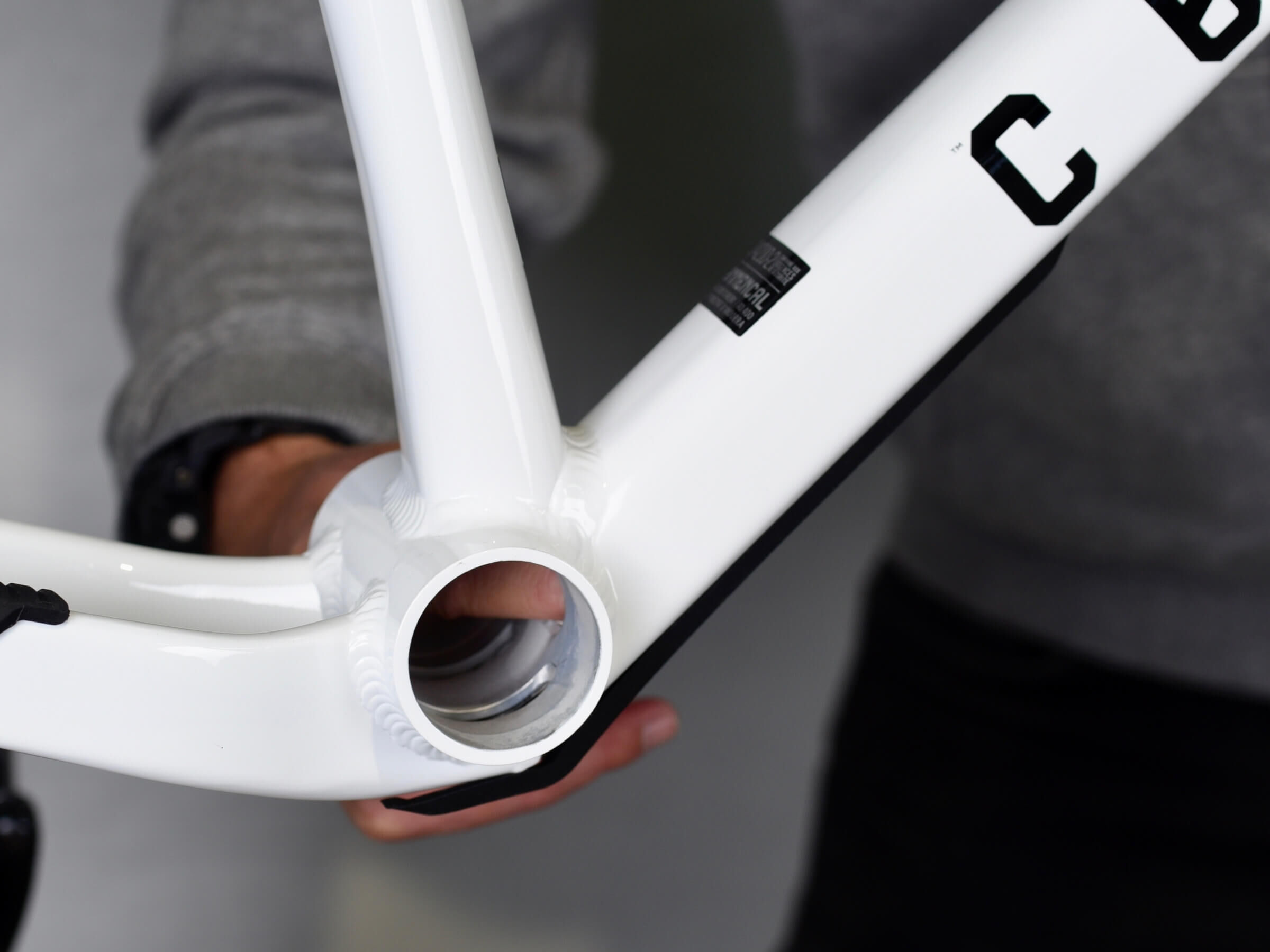
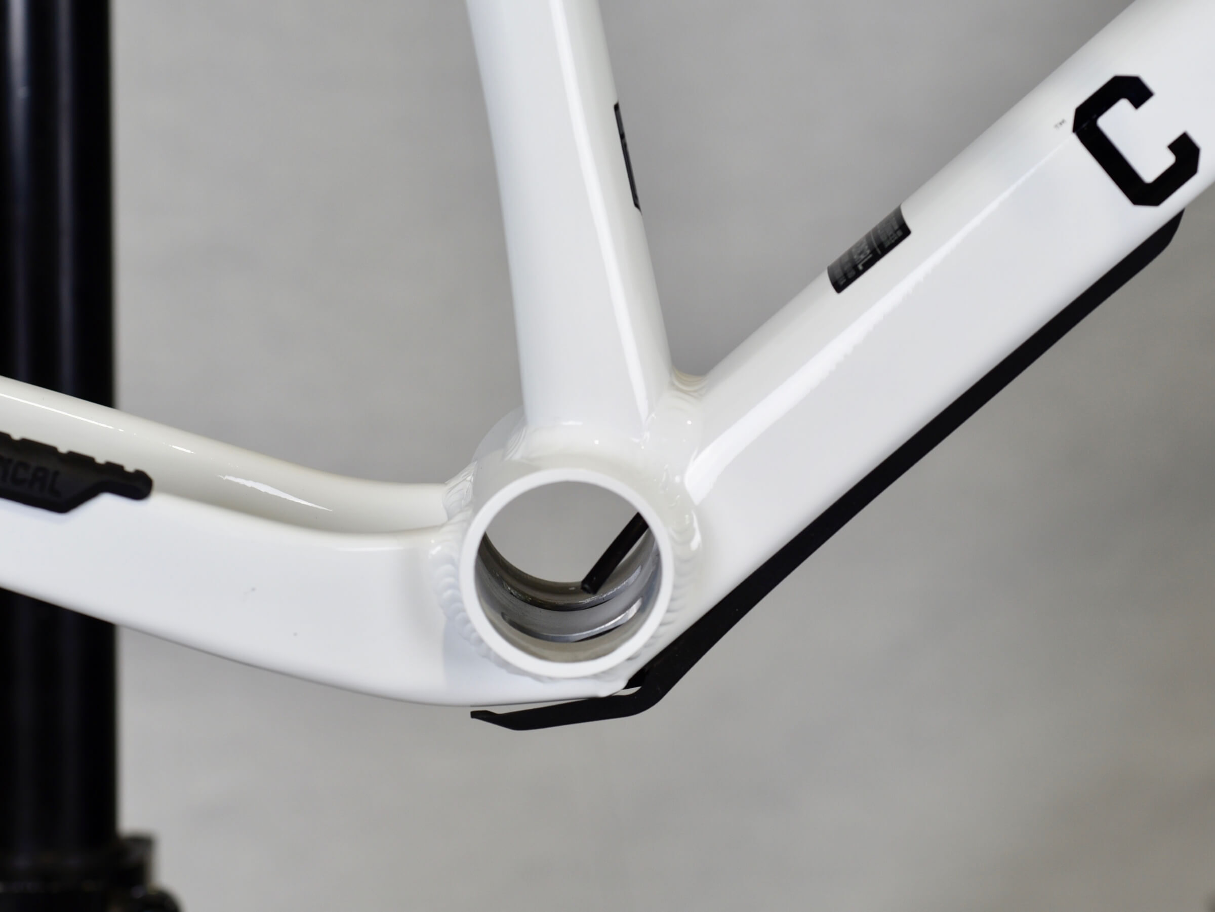
Now from the bottom bracket, route the cable in downtube, up to the headtube.
STEP 11
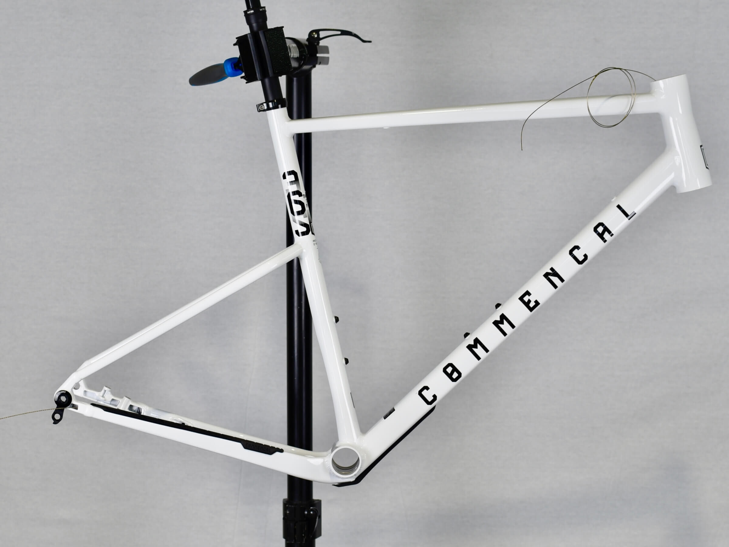
STEP 11
The cable is now routed from the back of chain stay, to the headtube.
STEP 12
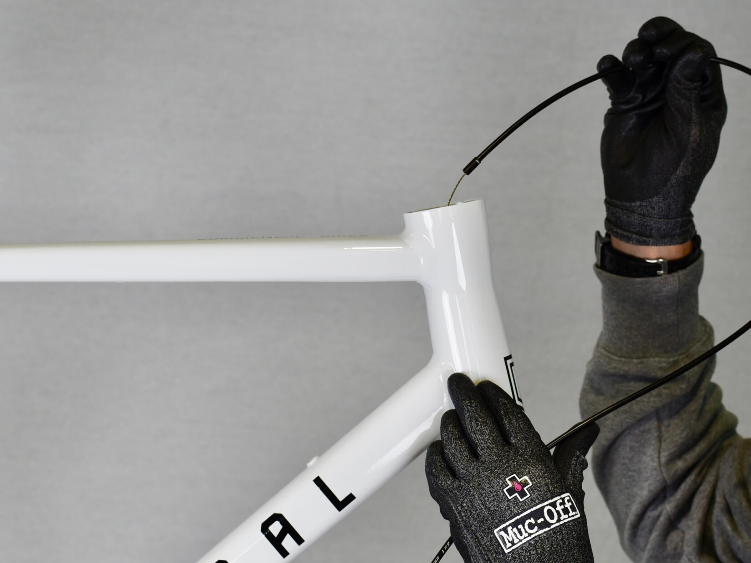
STEP 12
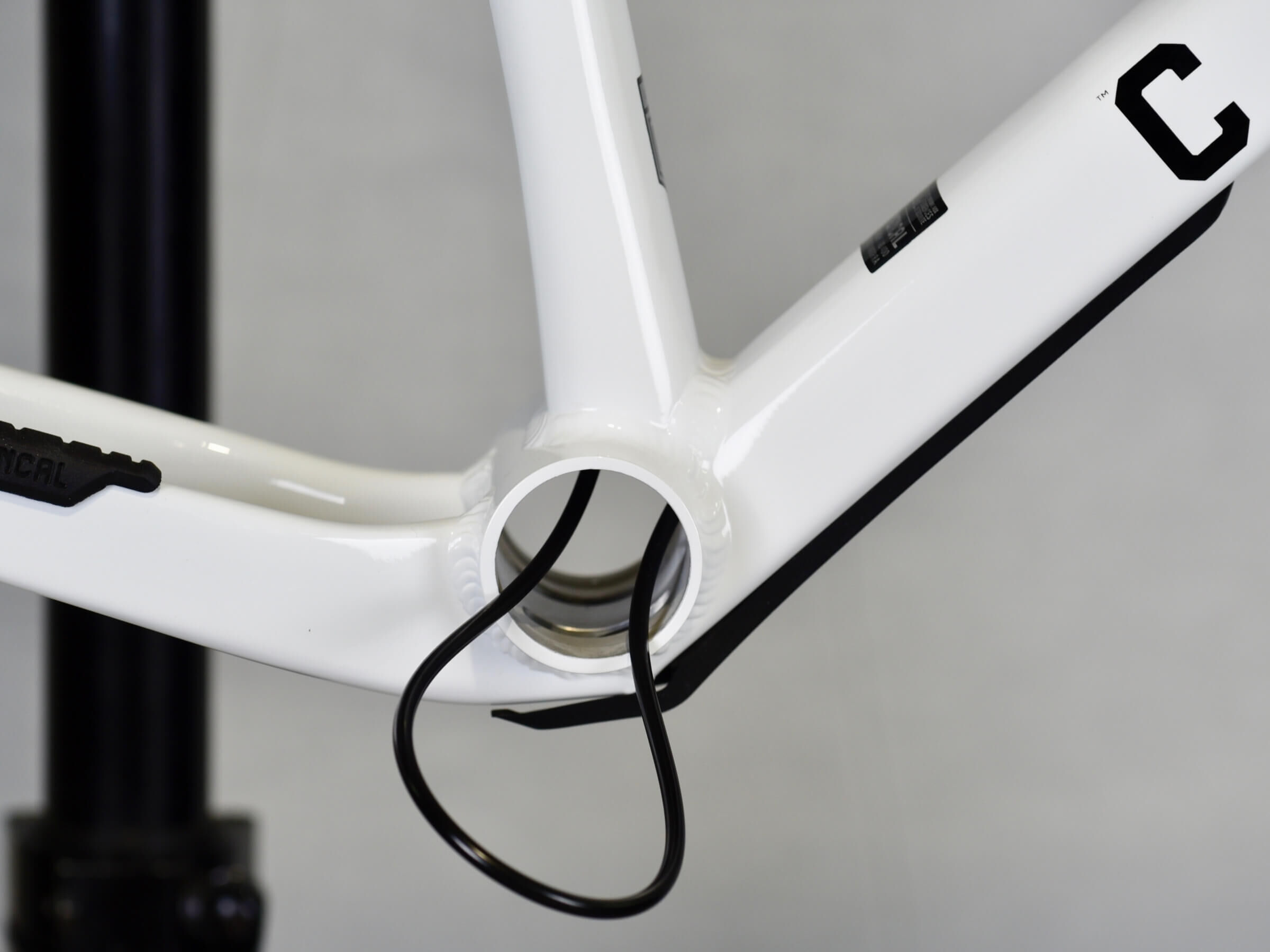
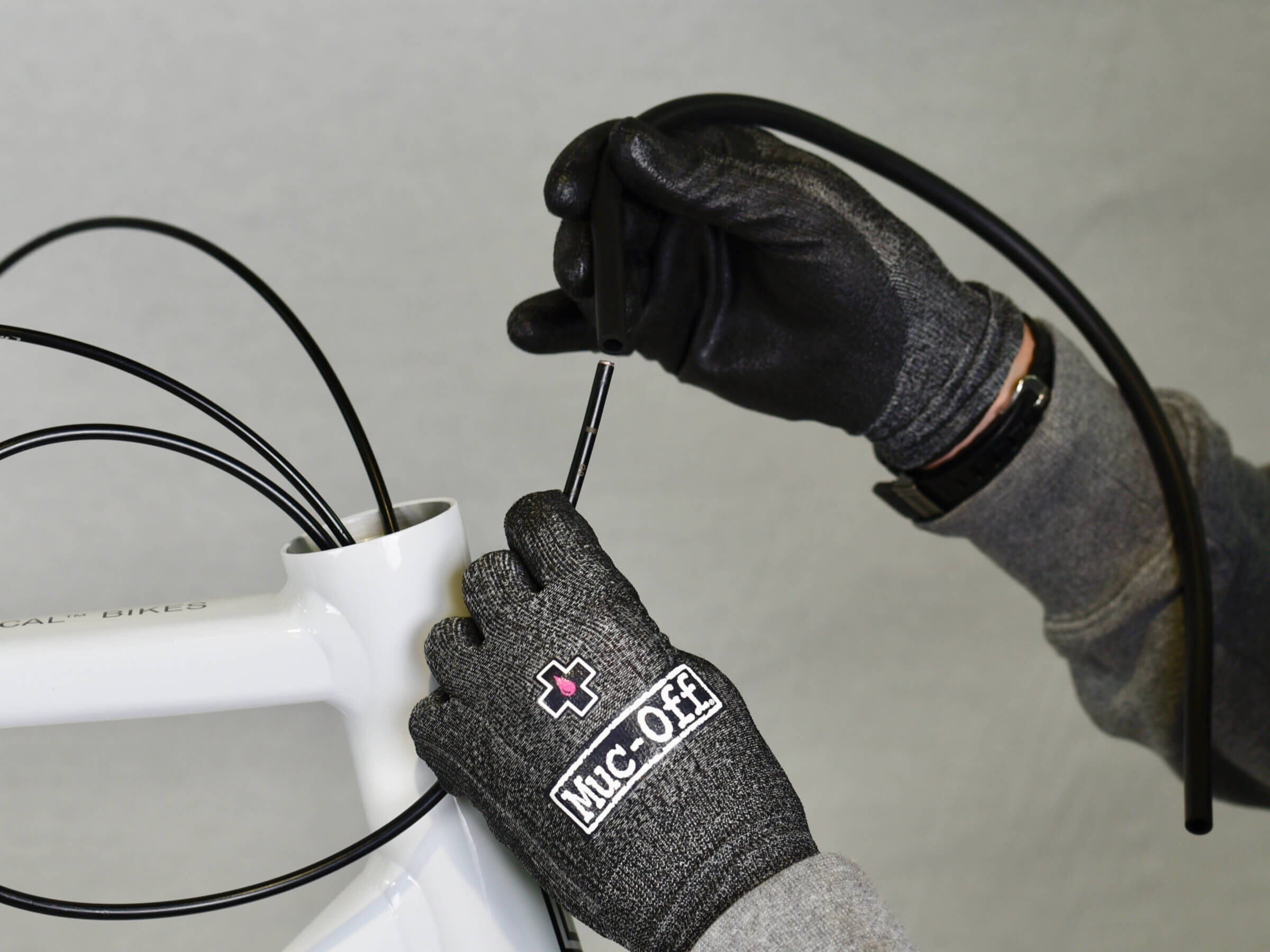
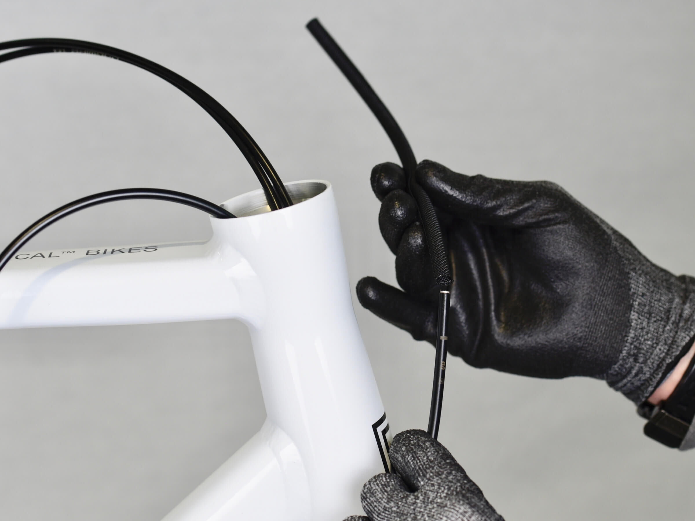
Use the cable as a guide, and route the housing from the headtube to the bottom bracket.
STEP 13
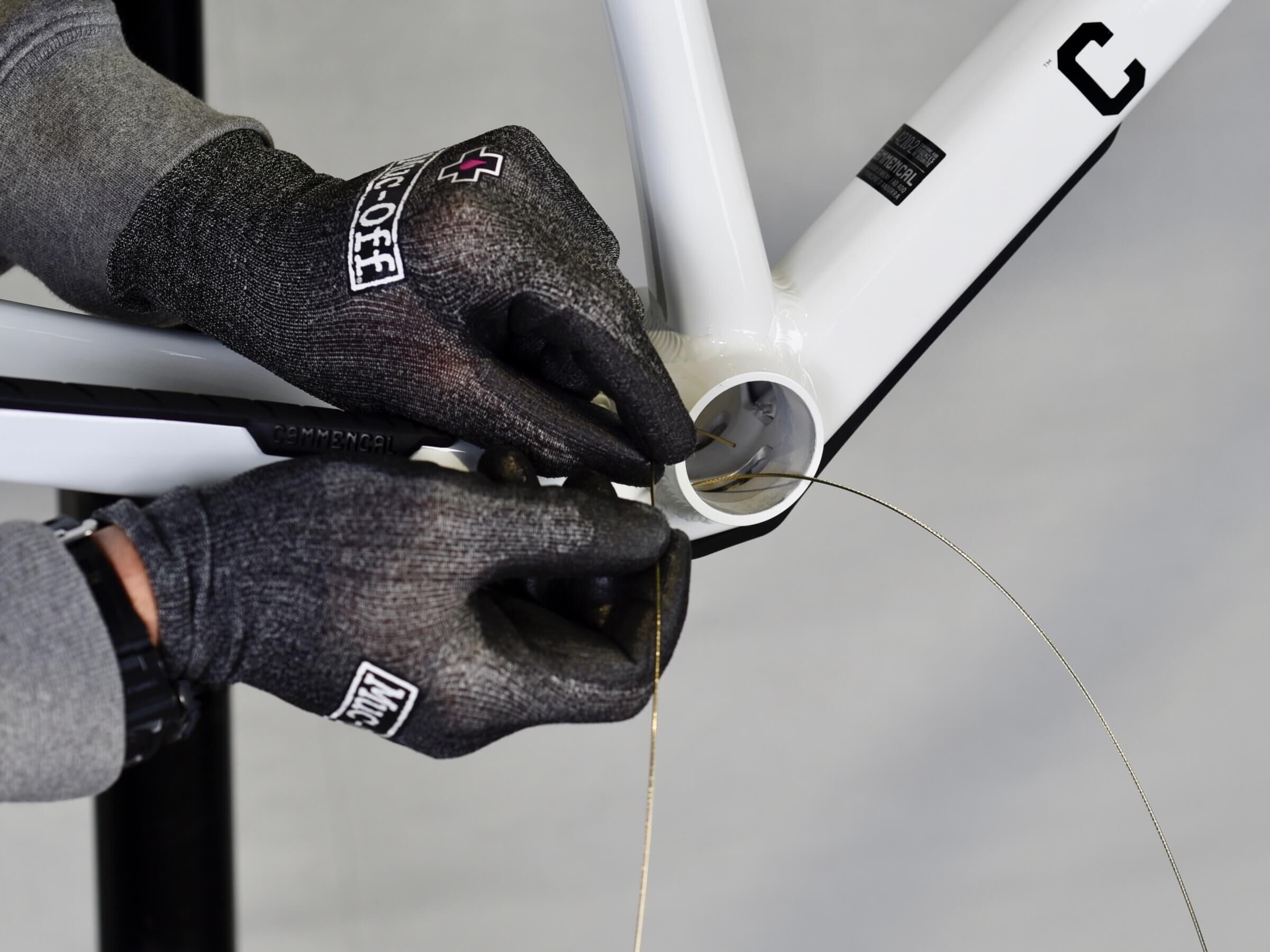
STEP 13
At bottom bracket level, push on the housing, to help it go through the chain stay.
STEP 14
STEP 14
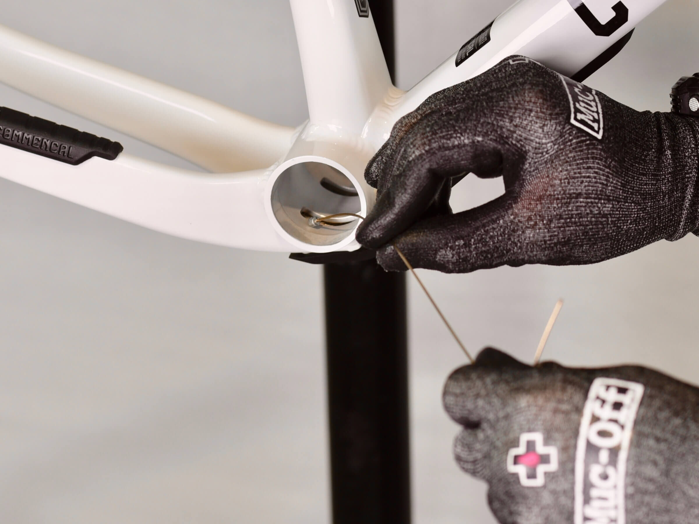
Use a pick to guide the housing out of the chain stay.
STEP 15
STEP 15
You can now remove the shifting cable from the housing.
Your derailleur housing is now routed in the frame.
STEP 16
STEP 16
Take out the front axle with the help of the 6mm Allen key.
STEP 17
STEP 17
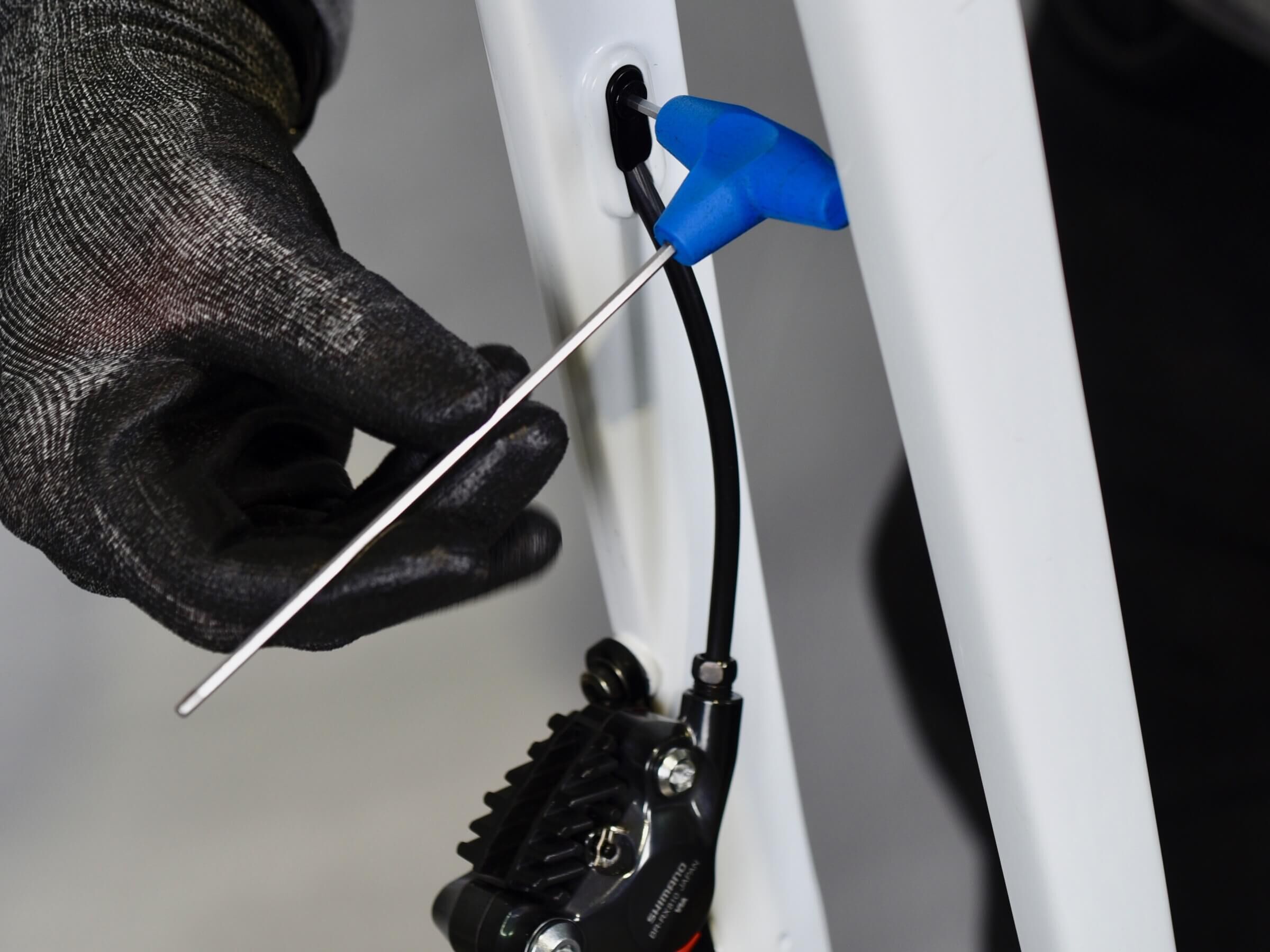
Route brake hose in the left chain stay, from back to front.
STEP 18
STEP 18
At bottom bracket level, push on the brake hose, to help it go through the downtube.
STEP 19
STEP 19
Then, route brake hose in the downtube, up to the headtube.
STEP 20
STEP 20
Your brake hose is now routed in the frame.
STEP 21
STEP 21
Next step is to route dropper post housing inside the frame.
Route housing from the headtube to the downtube and bottom bracket.
STEP 22
STEP 22
Dropper post housing will get out at bottom bracket.
STEP 23
STEP 23
Now, route dropper post housing in the seat tube, by pushing it from bottom bracket.
STEP 24
STEP 24
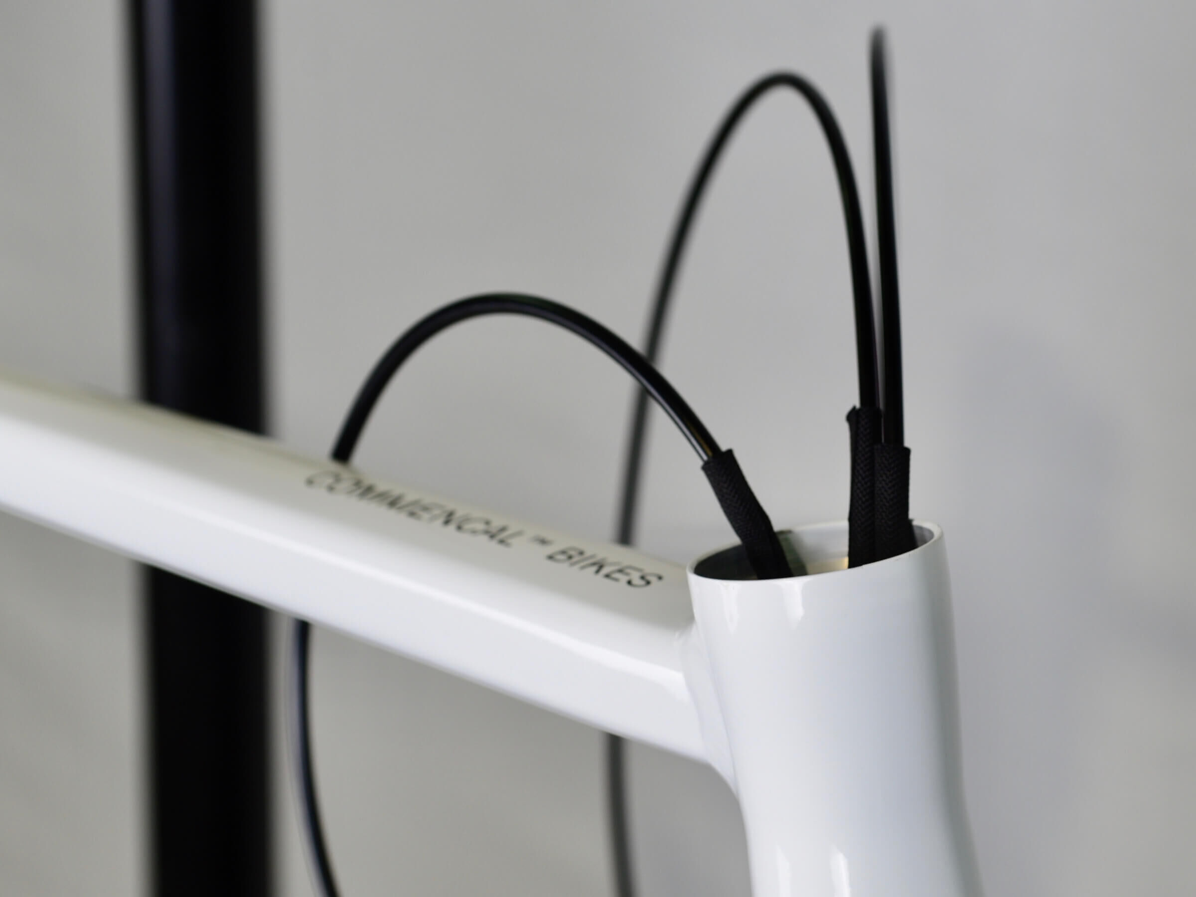
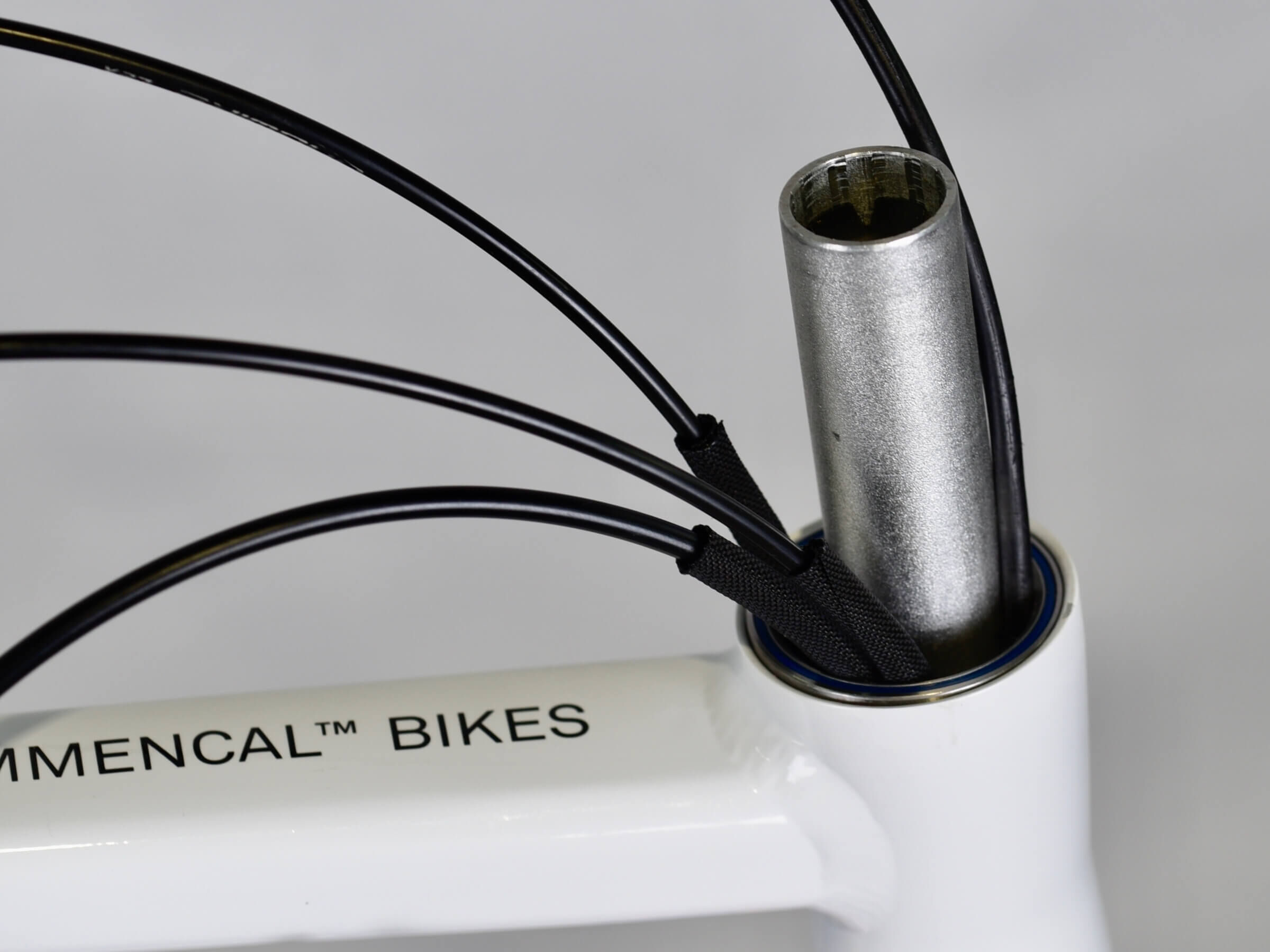
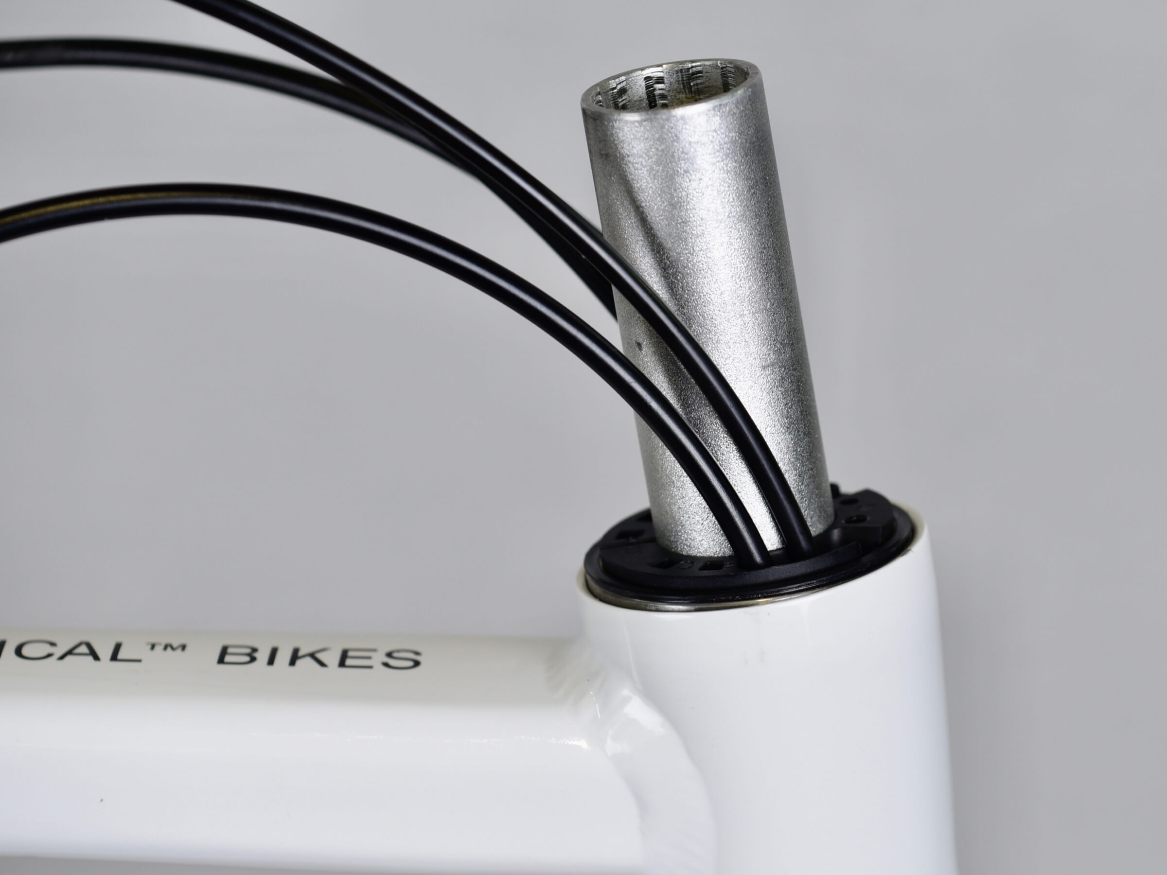
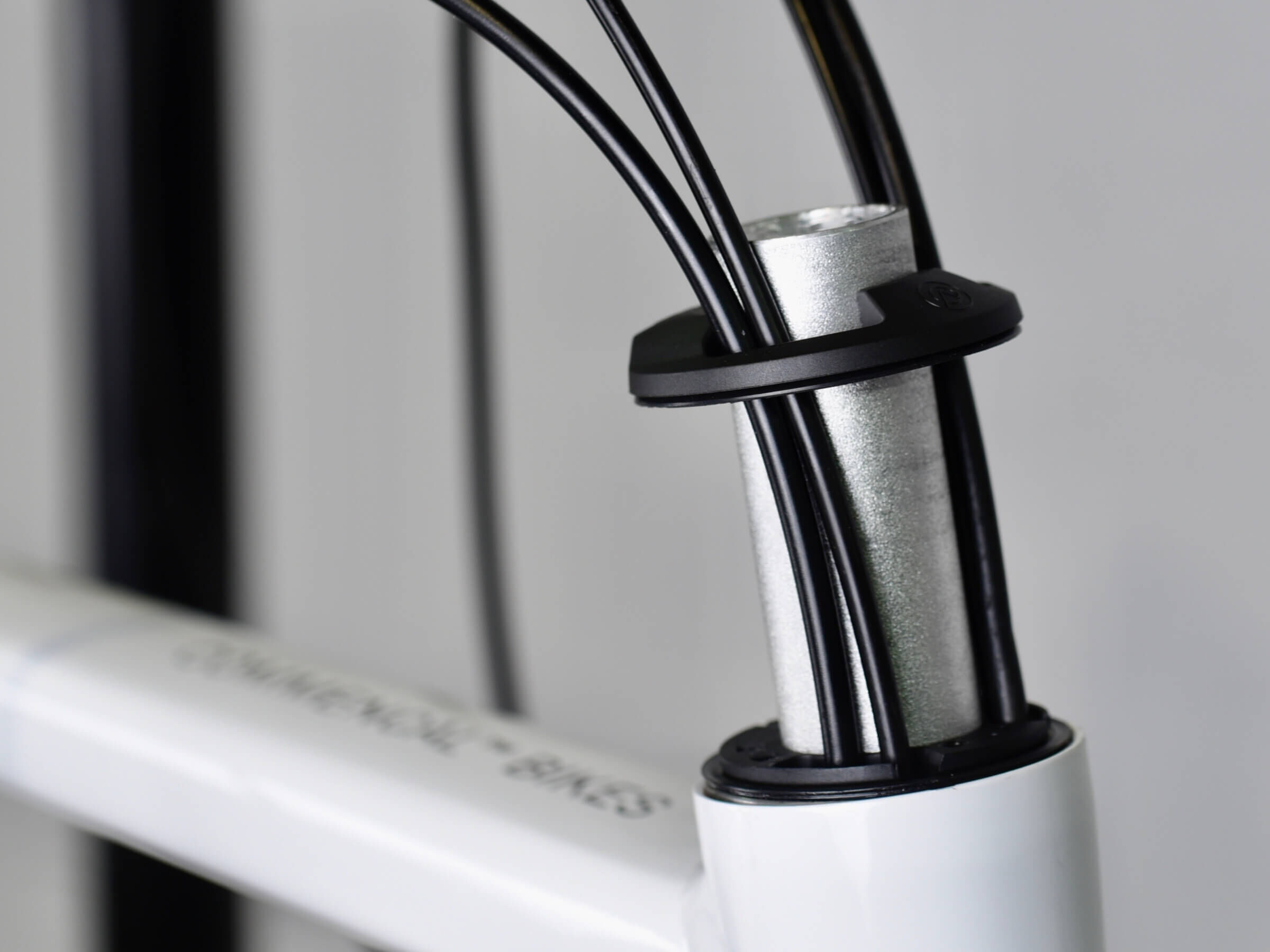
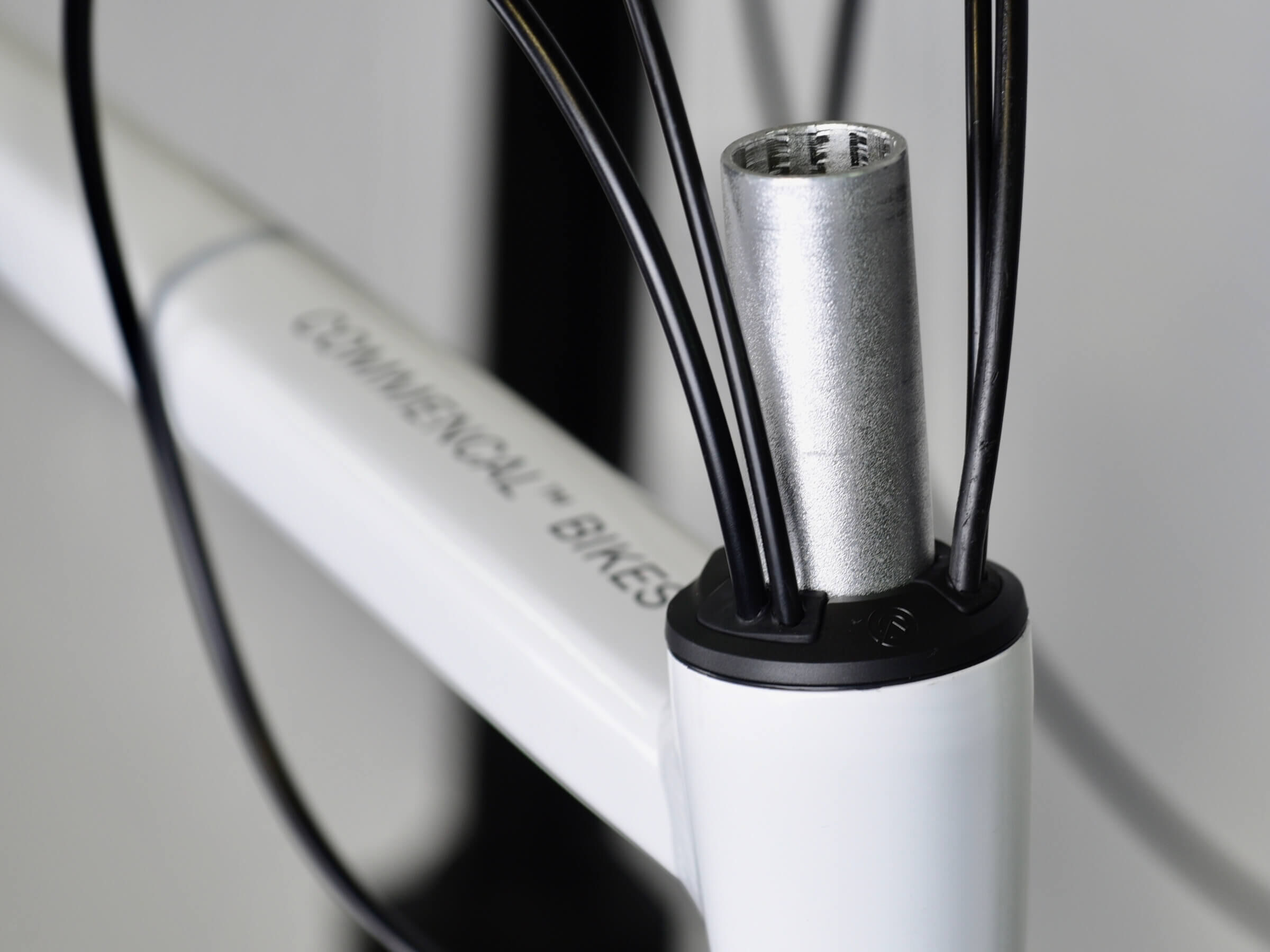
Now your derailleur, brake and dropper housing are getting out of the headtube.
STEP 25
STEP 25
Place foam tubes on each housing, to avoid any rattling noise inside downtube.
STEP 26
STEP 26
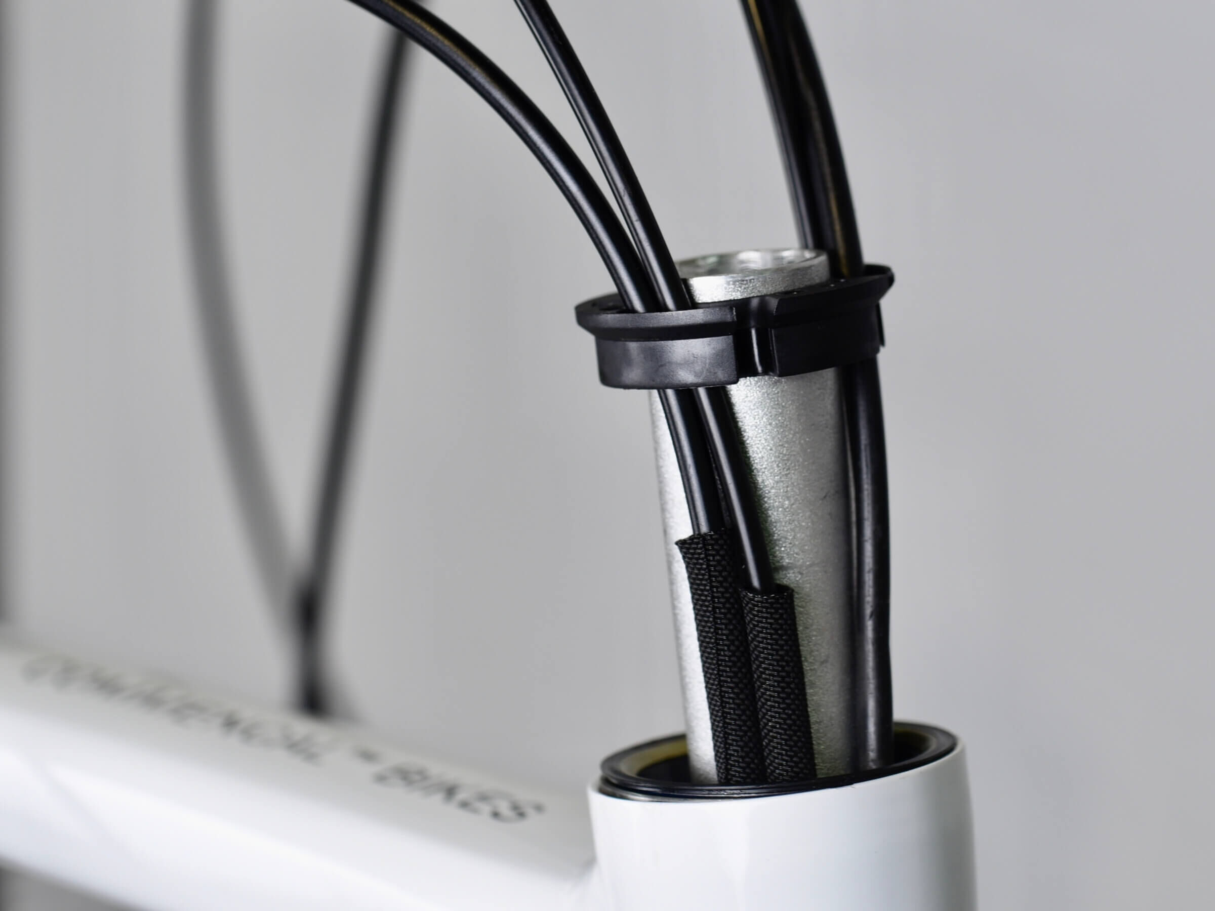
Now place nylon tubes on each housing, to avoid any rubbing on steerer.
STEP 27
STEP 27
Nylon tubes should be placed at upper bearing level.
To protect steerer, without getting in contact with headset compression ring.
STEP 28
STEP 28
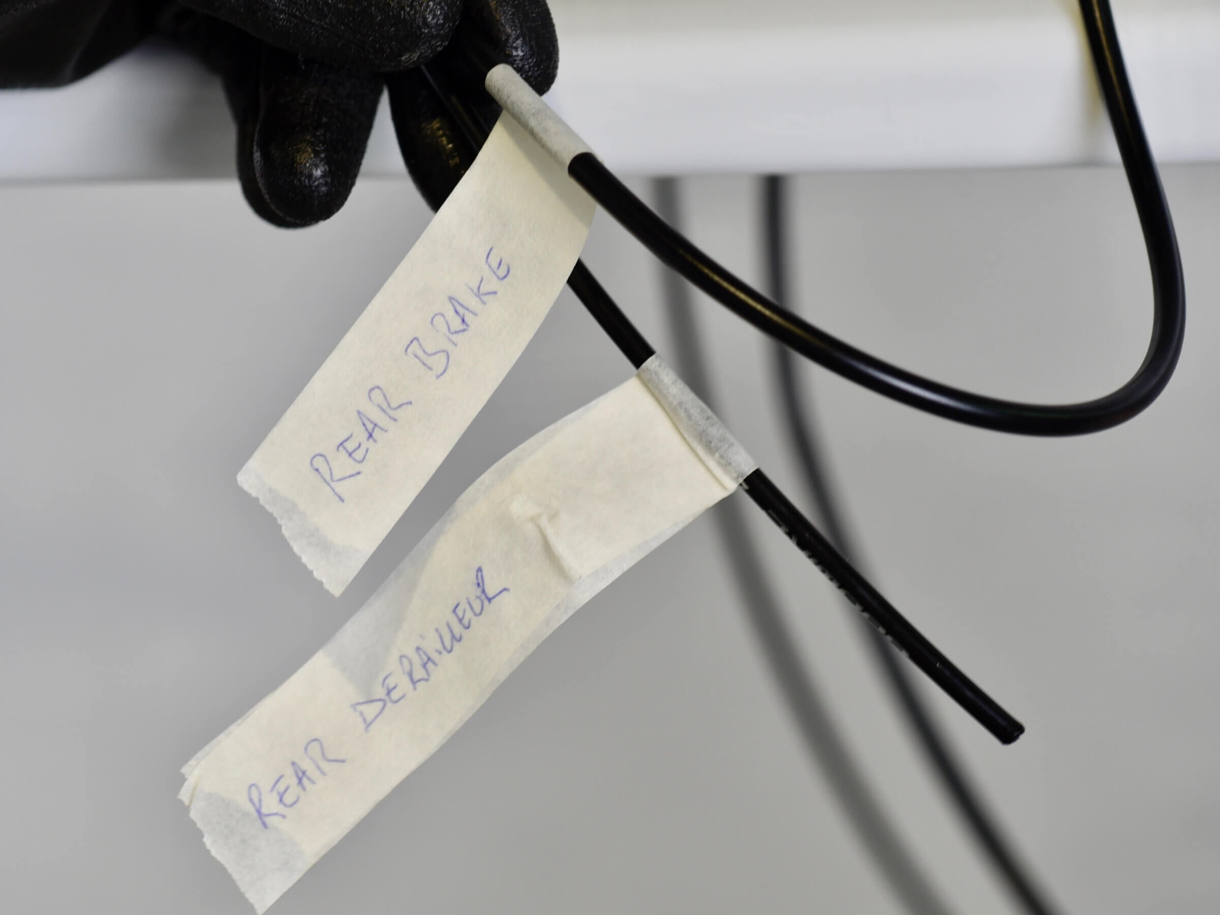
TIP: label the housings to don’t mix them while installing the headset.
STEP 29
STEP 29
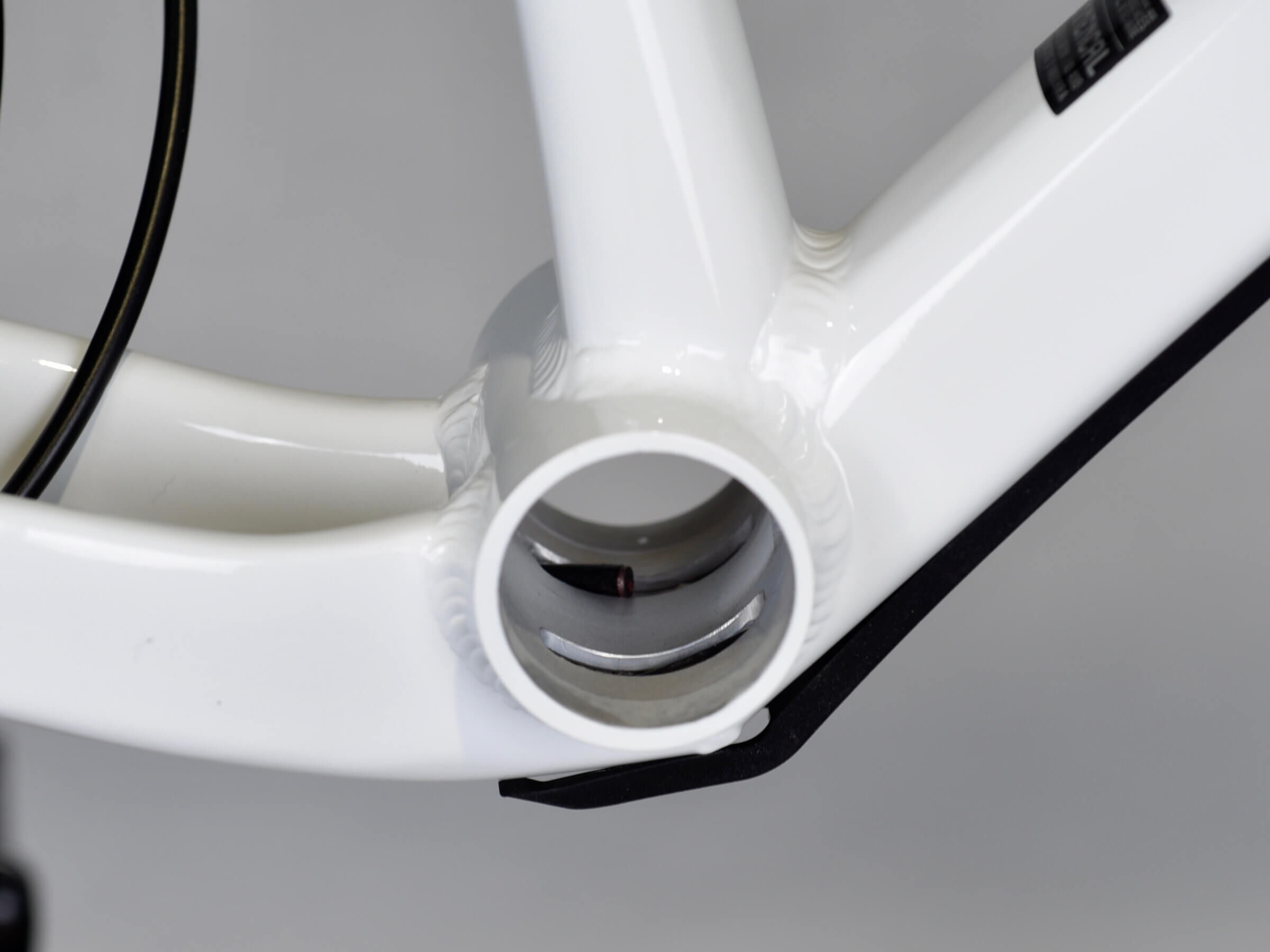
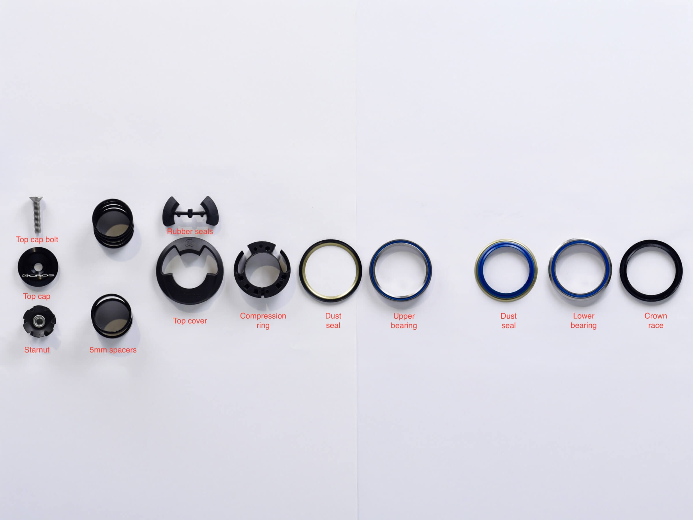
Prepare your Integrated Cable Routing headset.
STEP 30
STEP 30
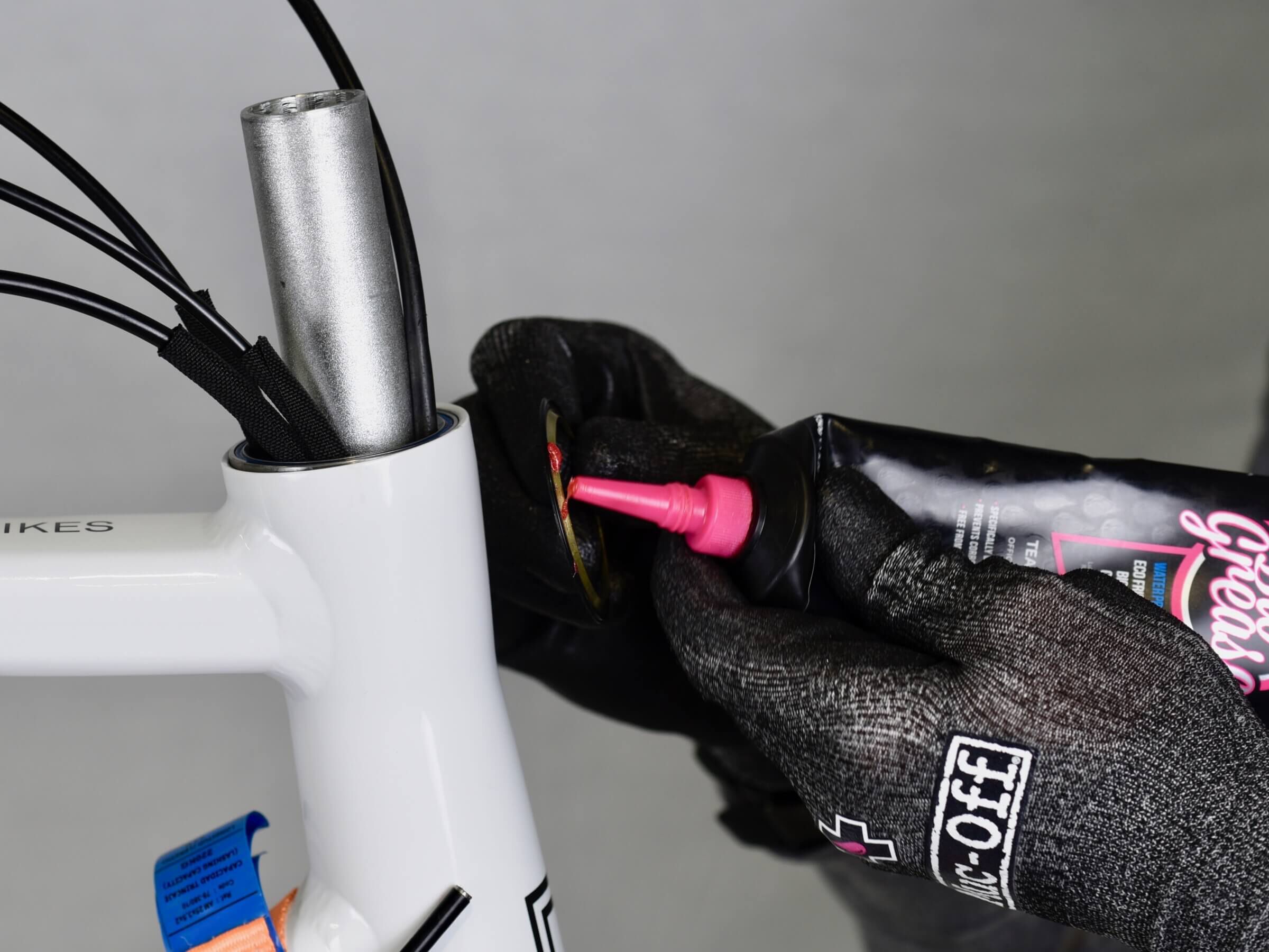
Now prepare your 365 fork.
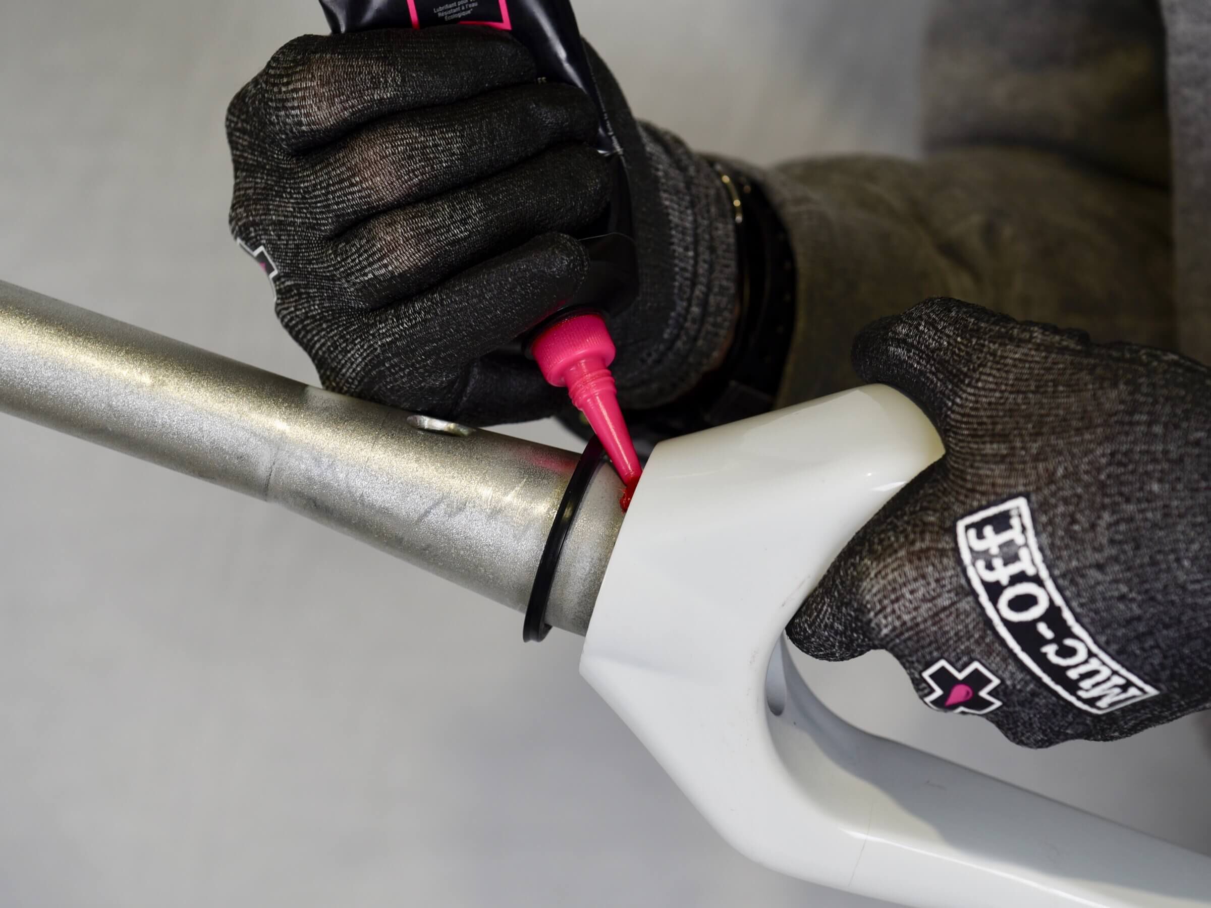
Grease steerer / crown race contact zone.
STEP 31
STEP 31
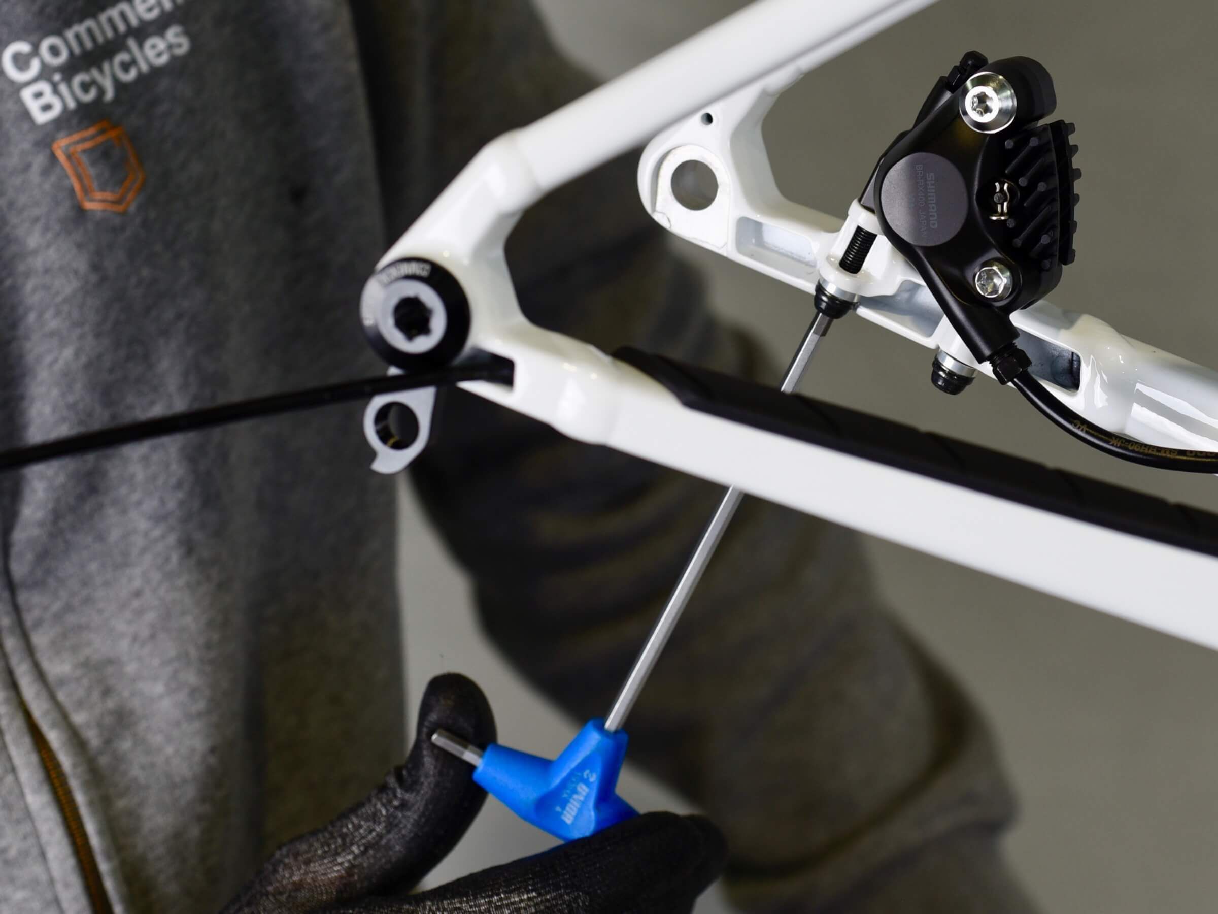
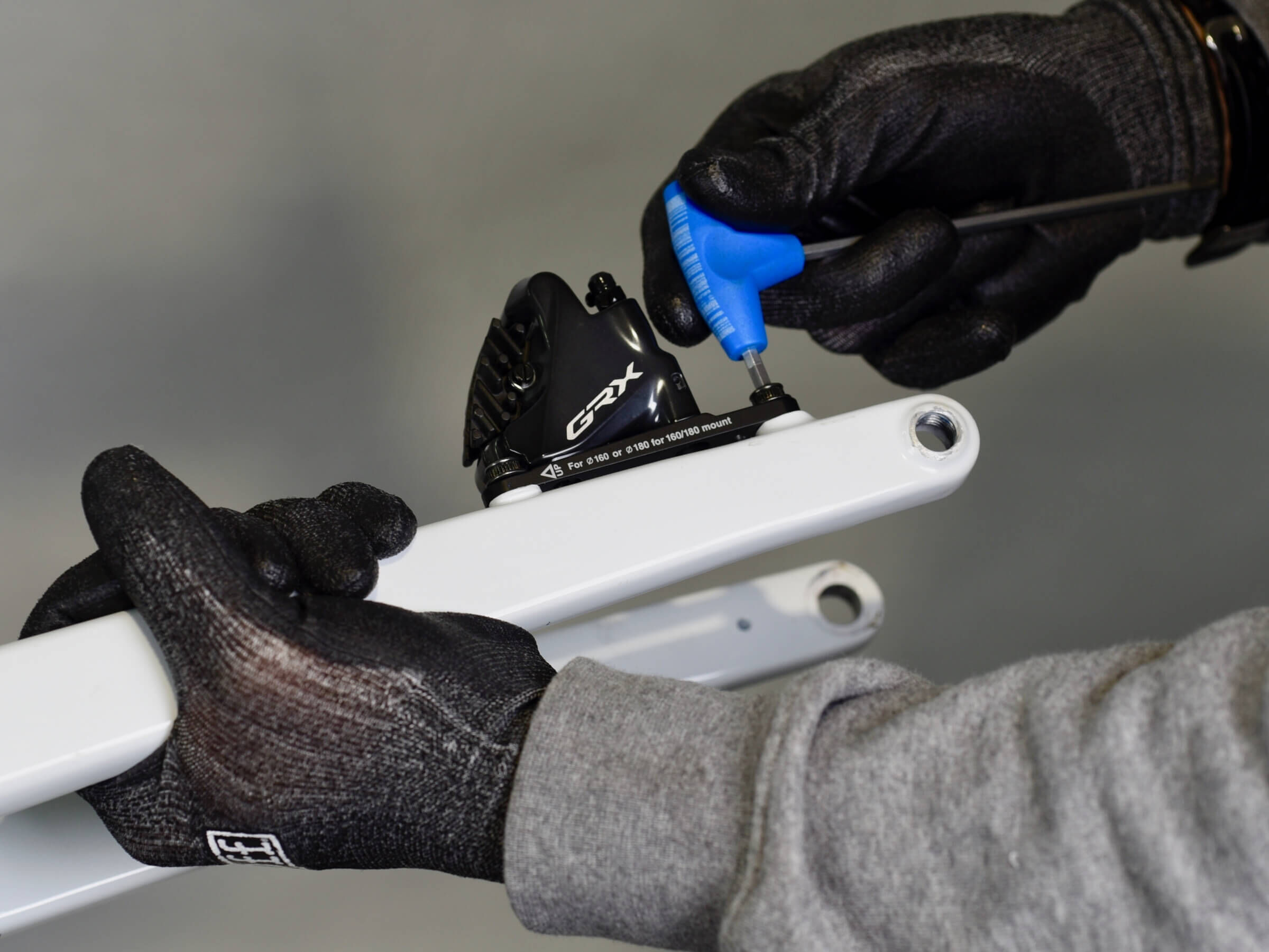
Install brake caliper on fork brake mount, with a 4mm Allen Key.
STEP 32
STEP 32
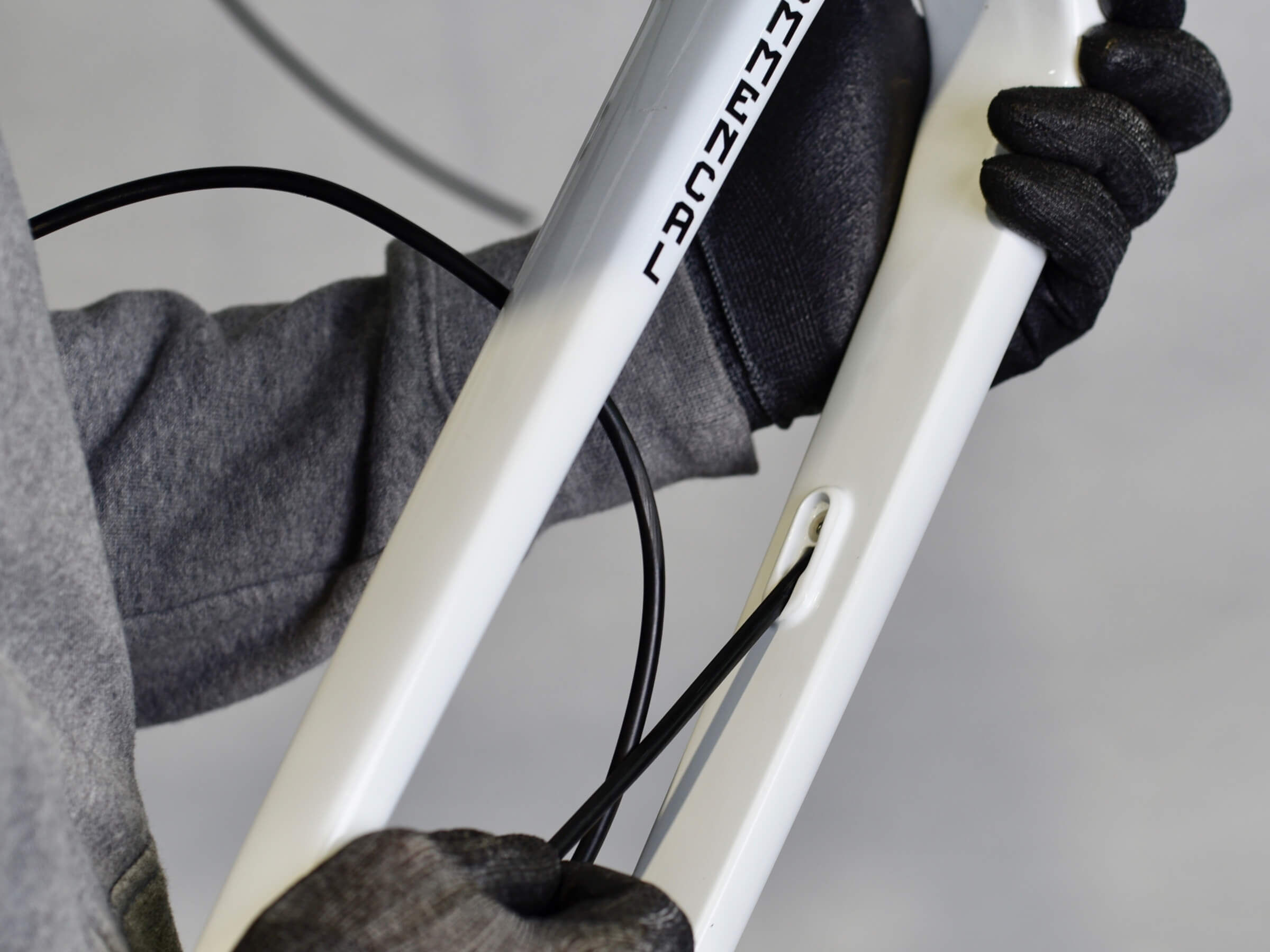
Route brake hose in the right fork leg, up to the steerer.
STEP 33
STEP 33
Then, route brake hose through the steerer hole.
STEP 34
STEP 34
Next step is to install fork and headset in the frame.
Grease headtube lower zone.
STEP 35
STEP 35
Grease crown race / lower bearing contact zone.
STEP 36
STEP 36
Place lower bearing dust seal.
STEP 37
STEP 37
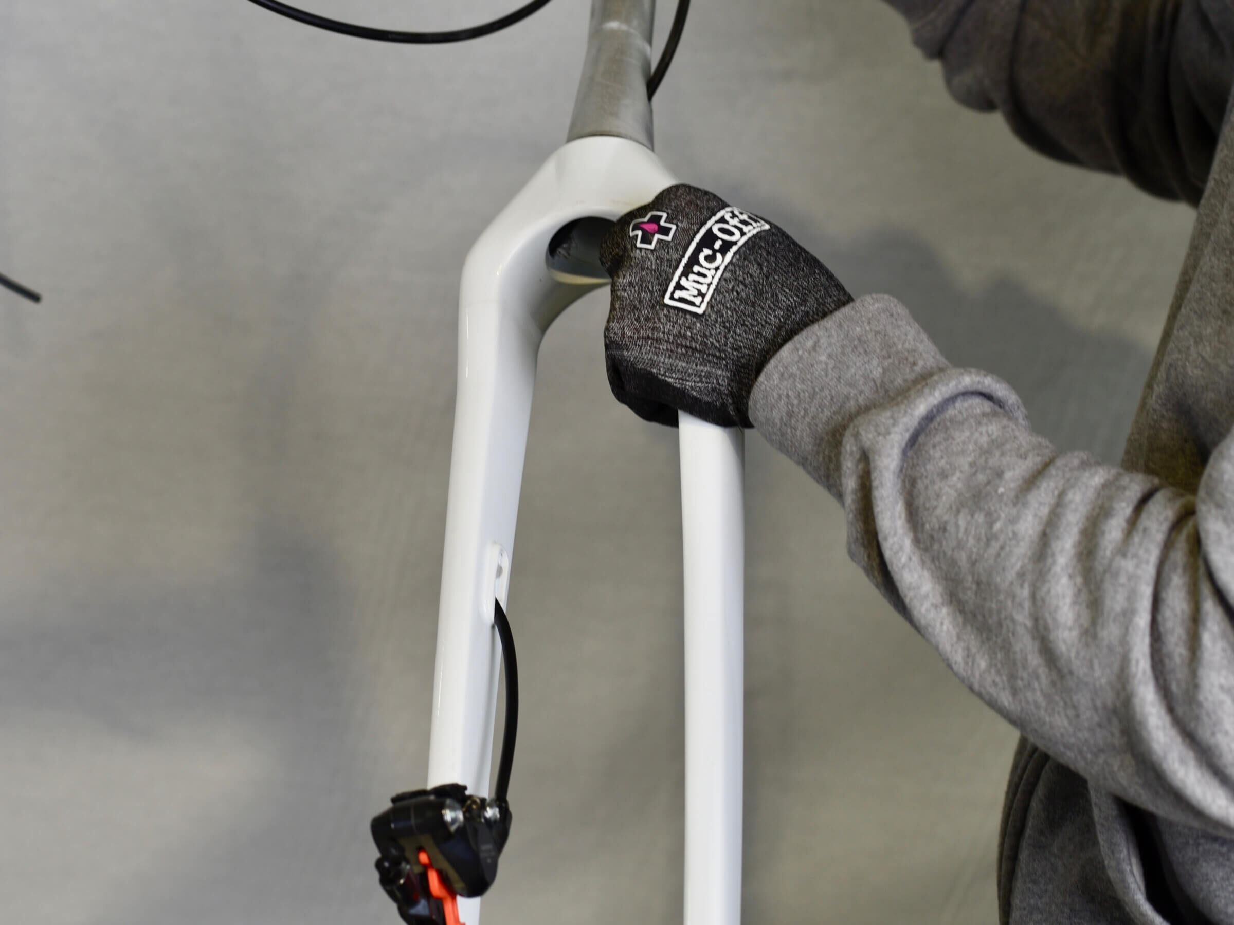
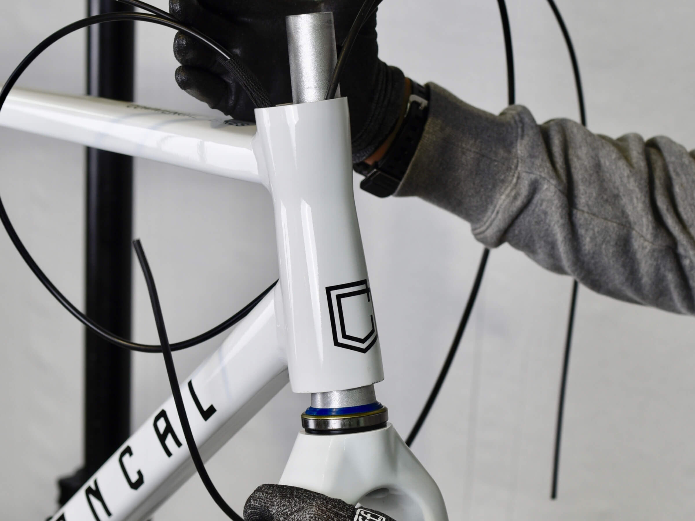
Now install fork in the headtube.
Make sure to place:
- Derailleur housing on right side of steerer.
- Rear brake hose on right side of steerer ( for continental style ) or left side of steerer ( for UK / moto style ).
- Dropper post housing on left side of steerer.
- Front brake hose on left side of steerer ( for continental style ) or right side of steerer ( for UK / moto style ).
STEP 38
STEP 38
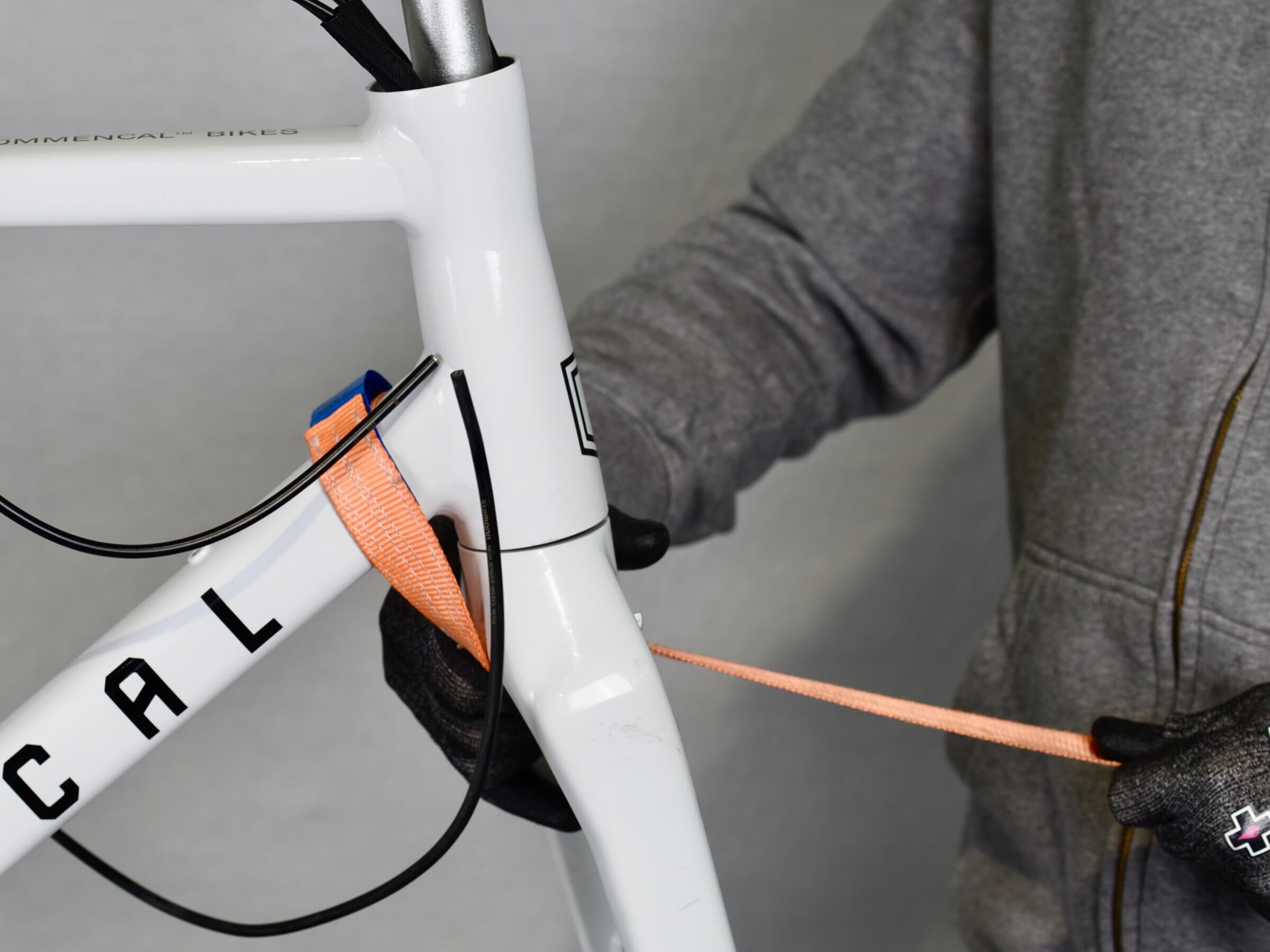
Use a strap to keep the fork in place, while installing headset upper parts.
STEP 39
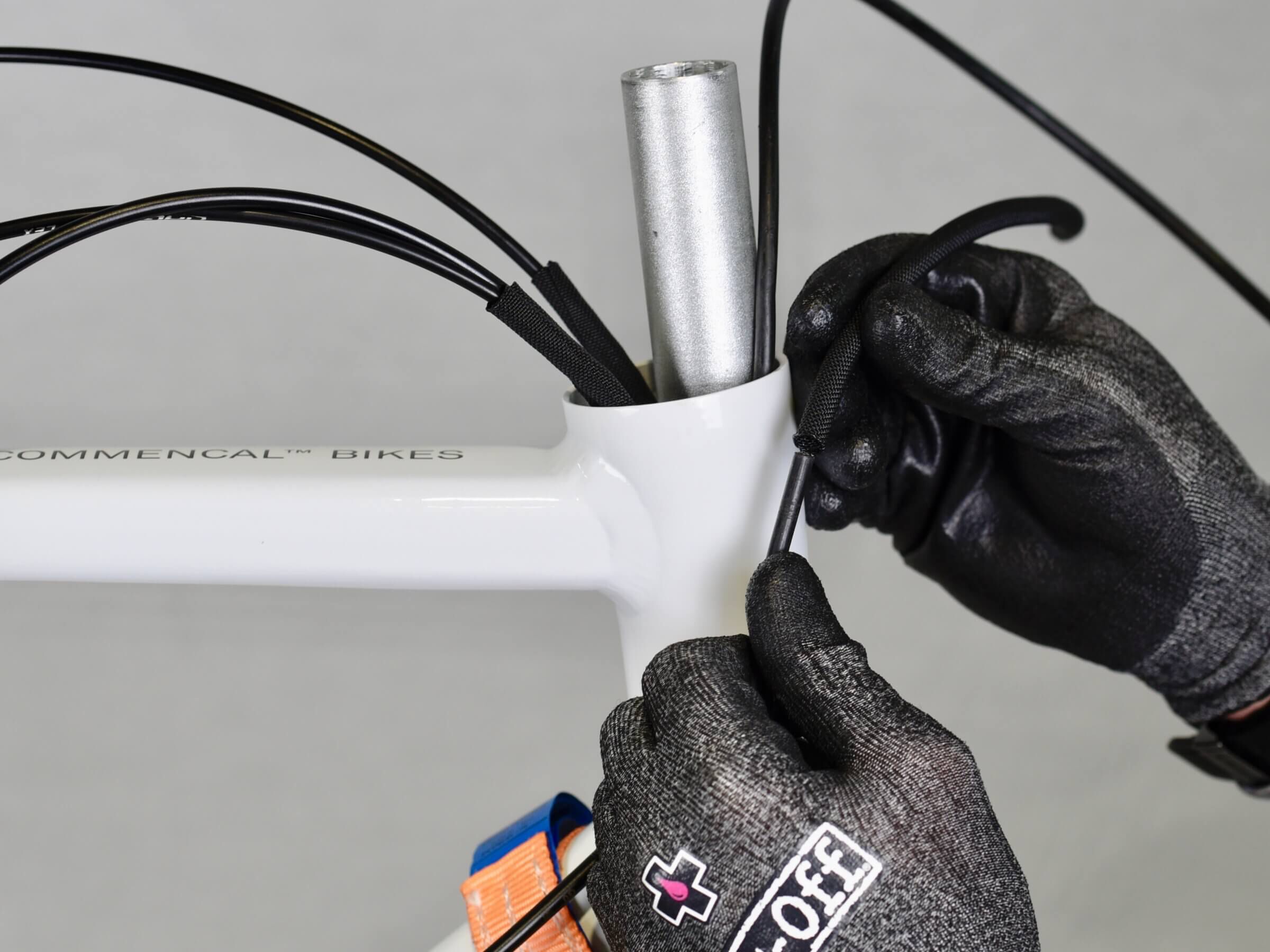
STEP 39
Place nylon tube on front brake housing, to avoid any rubbing on steerer.
STEP 40
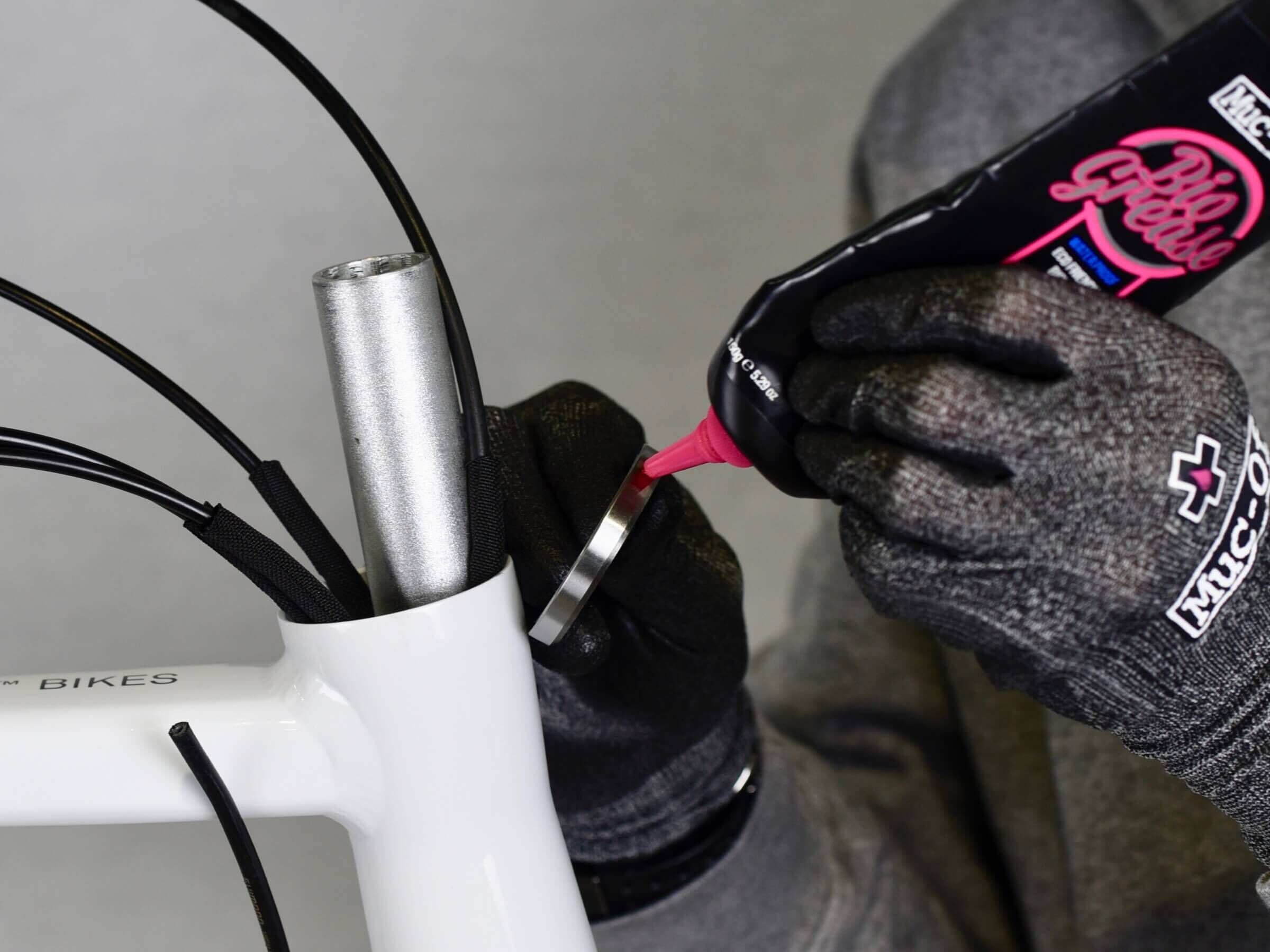
STEP 40
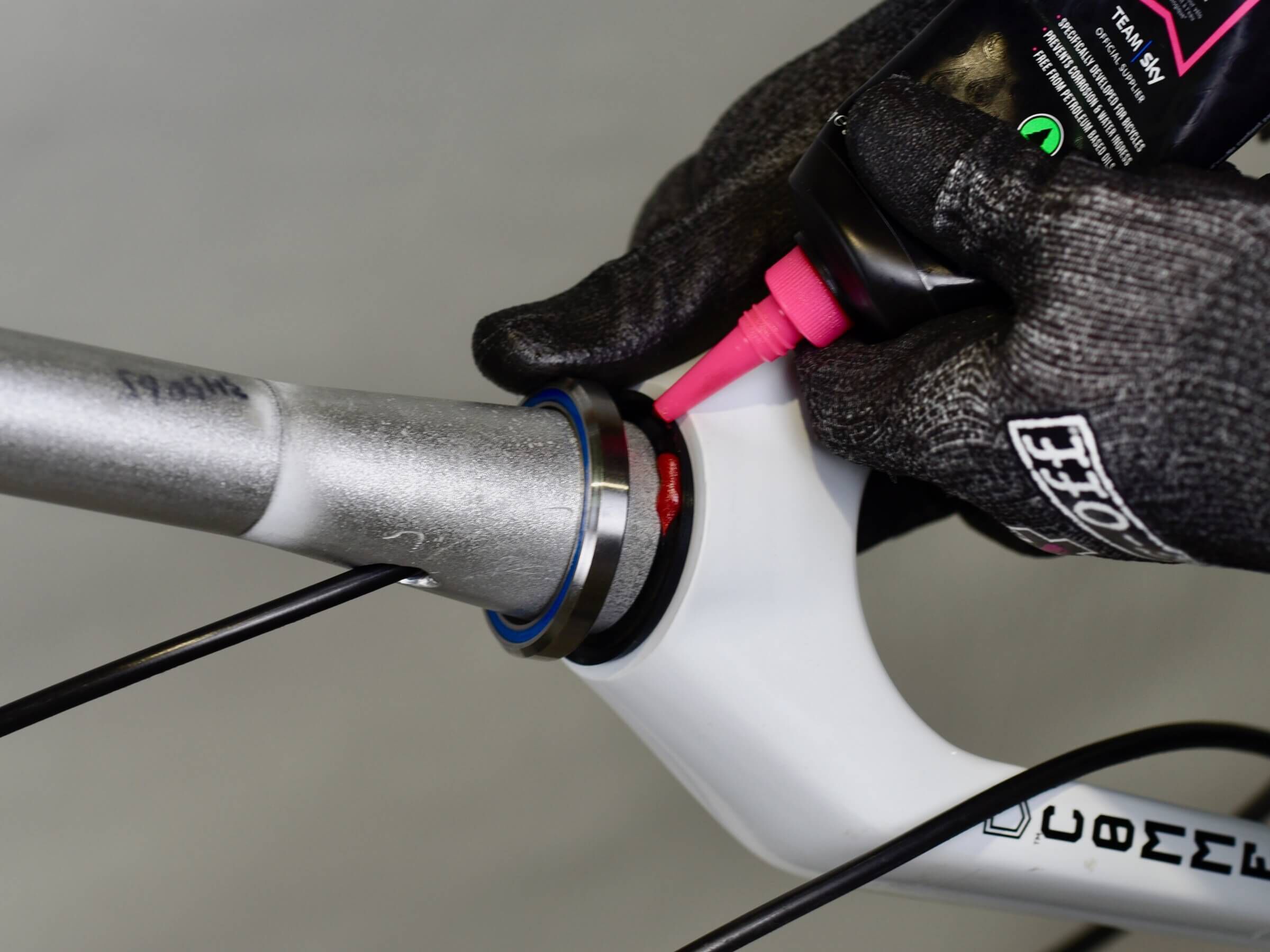
Grease headtube upper zone and bearing.
STEP 41
STEP 41
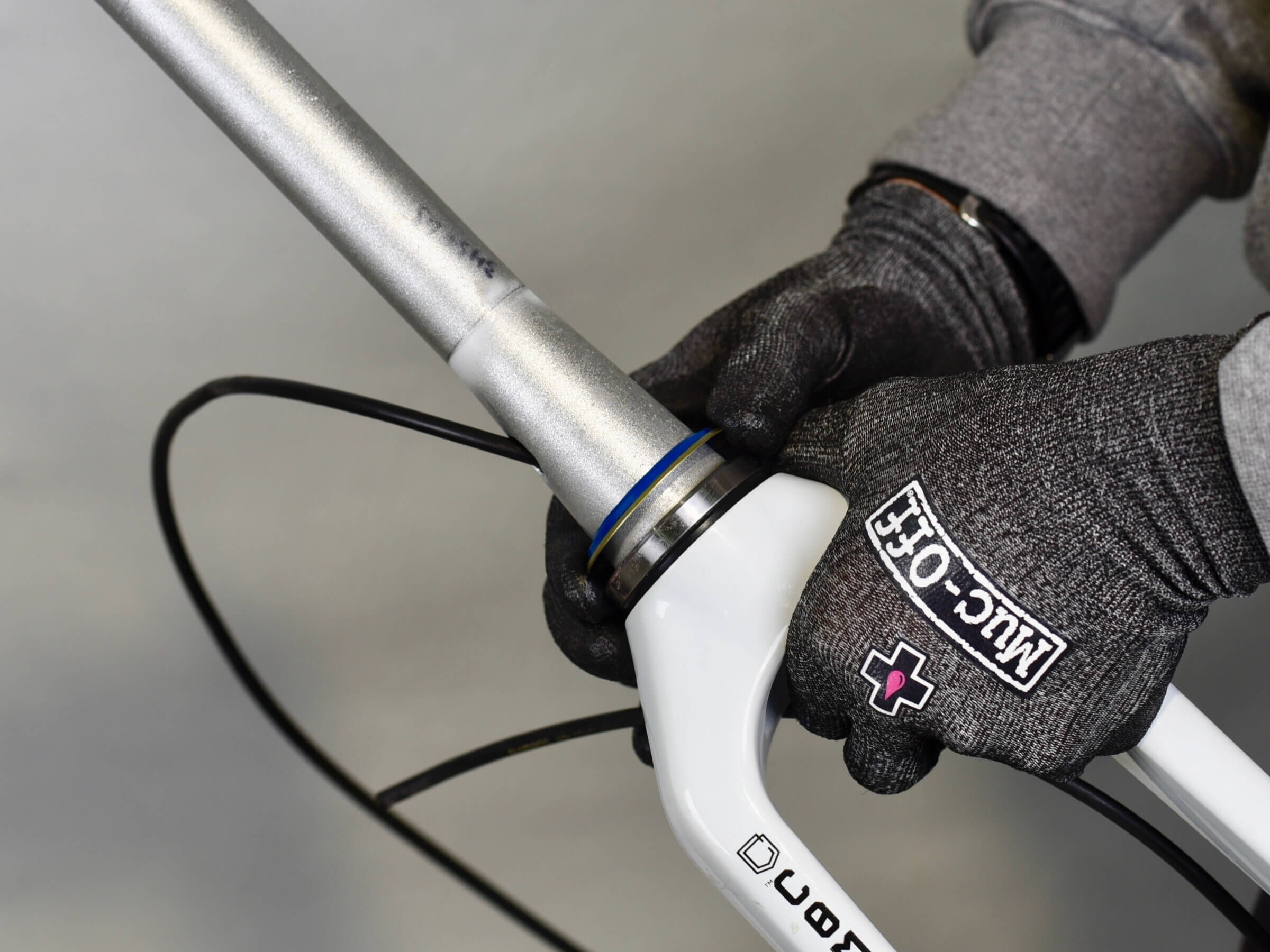
Install upper bearing.
STEP 42
STEP 42
Grease smaller dust seal, and install it on upper bearing.
STEP 43
STEP 43
Install compression ring, with housing placed on their channel.
STEP 44
STEP 44
Push compression ring at bearing contact.
STEP 45
STEP 45
Install top cover on steerer, with housing placed in their channel.
STEP 46
STEP 46
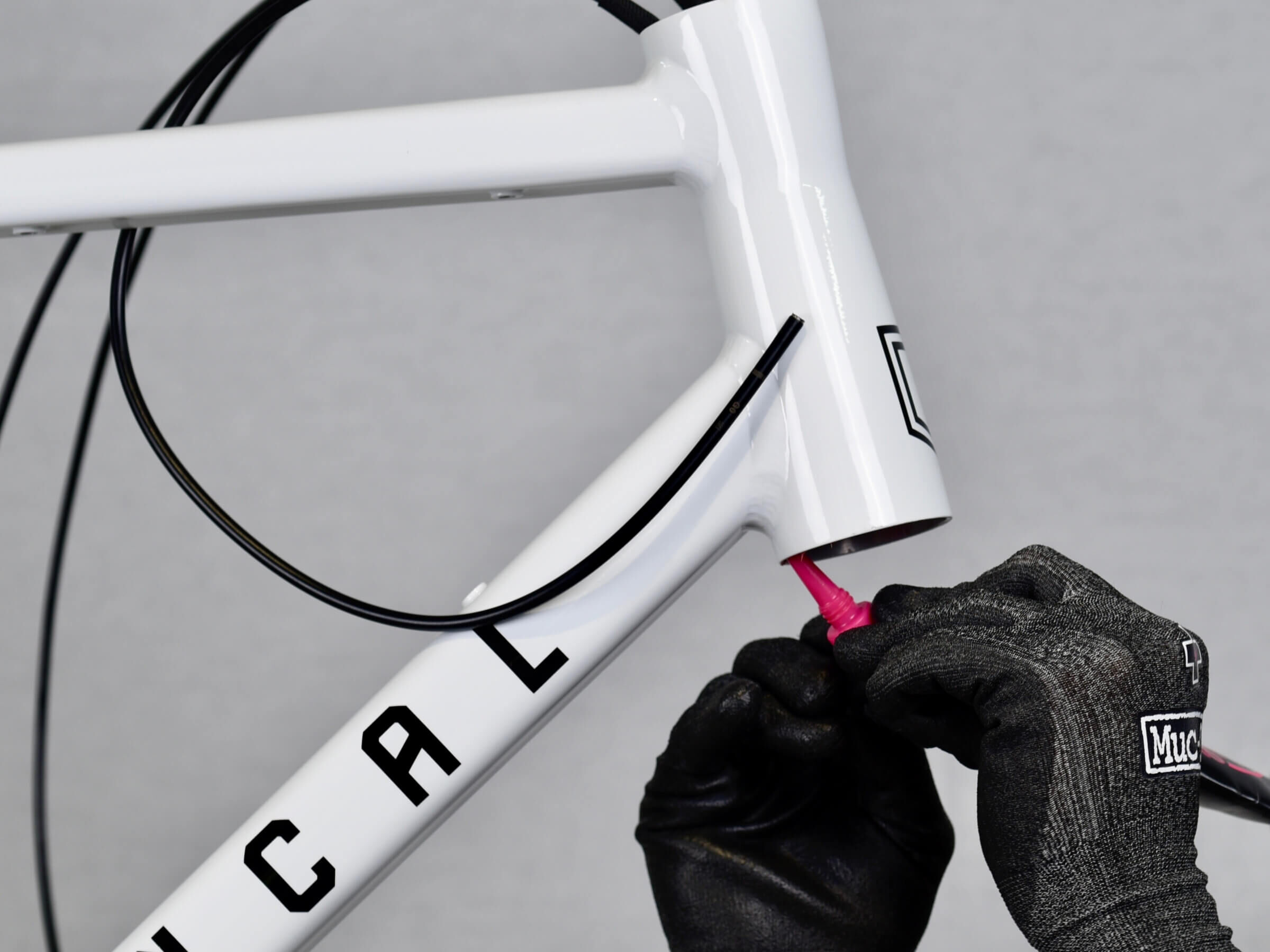
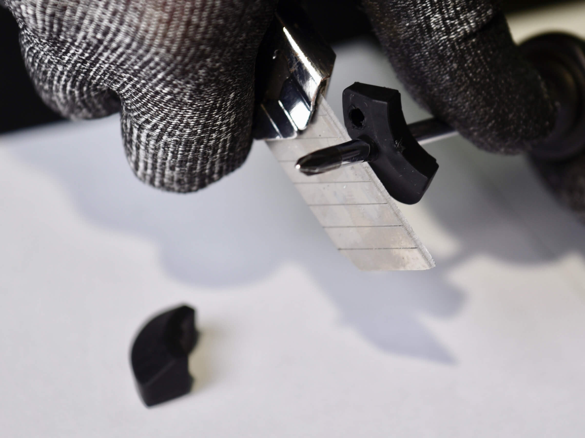
Now use the Philips screwdriver to open rubber seals according to your setup.
NOTE: seals have a specific right and left side, make sure to identify them correctly.
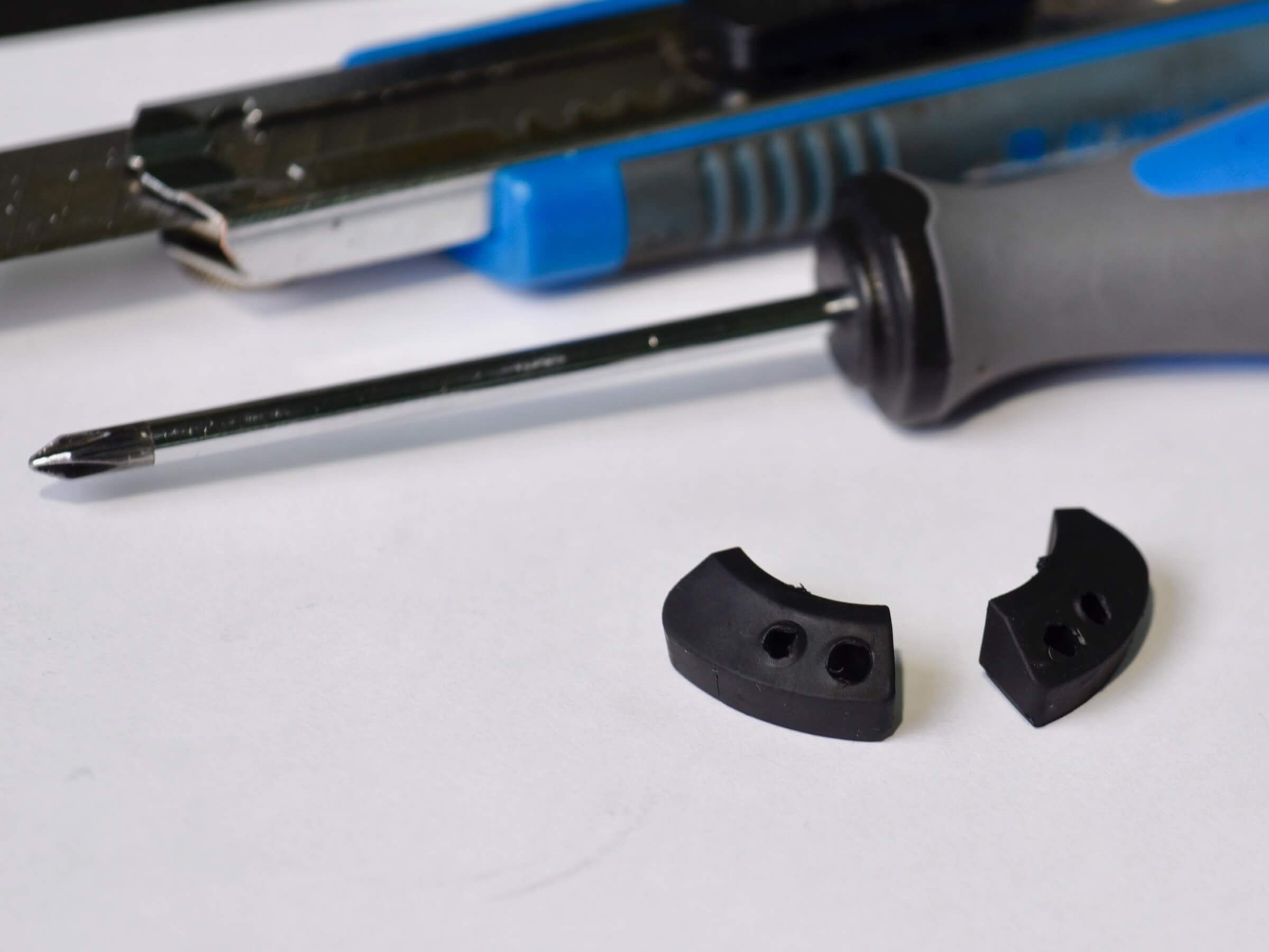
Cut rubber excess using cutters.
STEP 47
STEP 47
Your rubber seals are now ready to be installed.
STEP 48
STEP 48
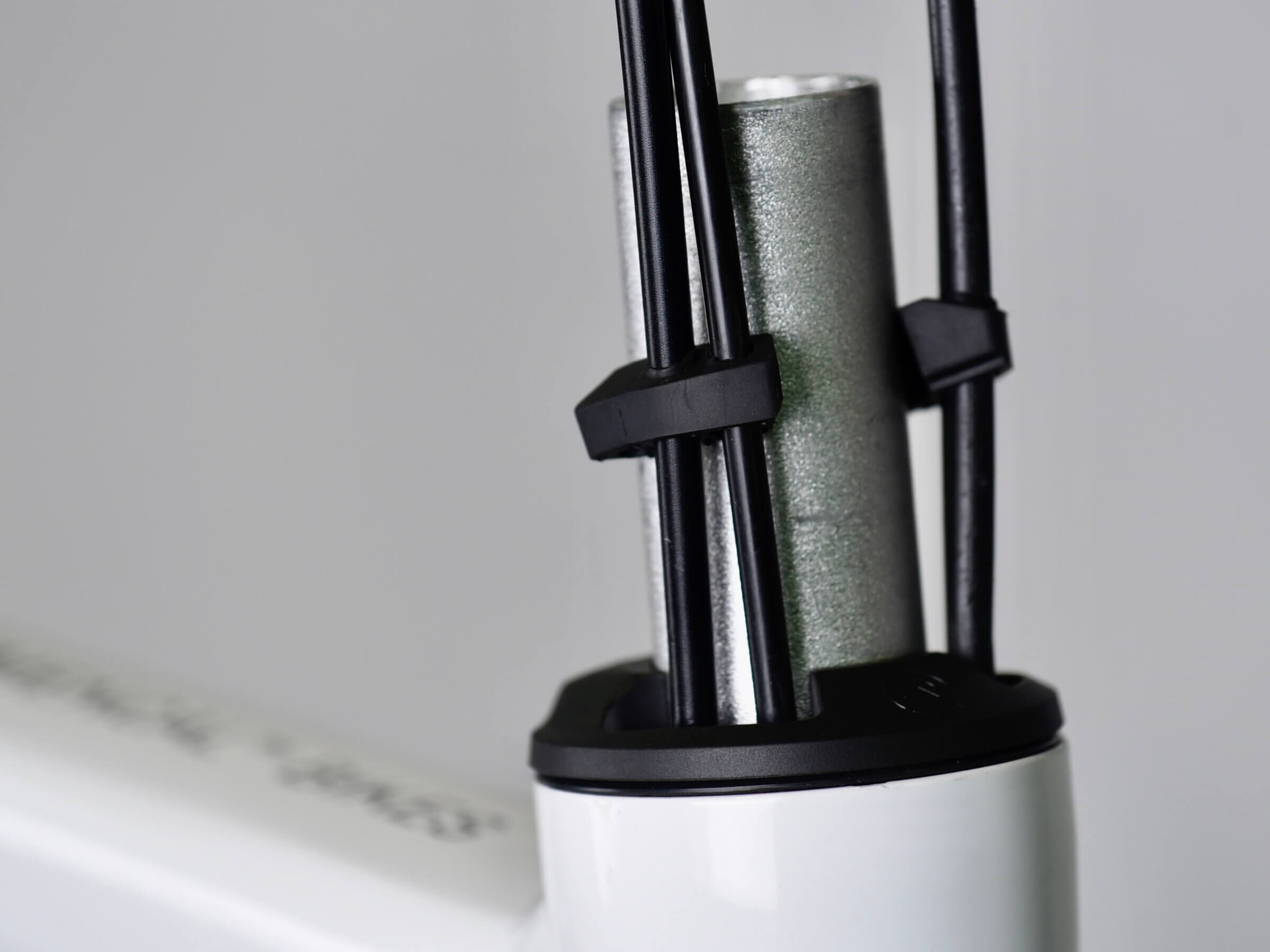
Install rubber seals on housing.
STEP 49
STEP 49
Push rubber seals in the top cover.
STEP 50
STEP 50
Now install headset spacers, stem and top cap. Use a Allen key to screw top cap bolt.
If needed, mark and cut the fork at correct length, and install star nut in the steerer.
STEP 51
STEP 51
Place fork cable guide, and tighten the bolt with a 2,5mm Allen key.
STEP 52
STEP 52
Place chain stay cable guide, and tighten the bolt with a 2,5mm Allen key.
STEP 53
STEP 53
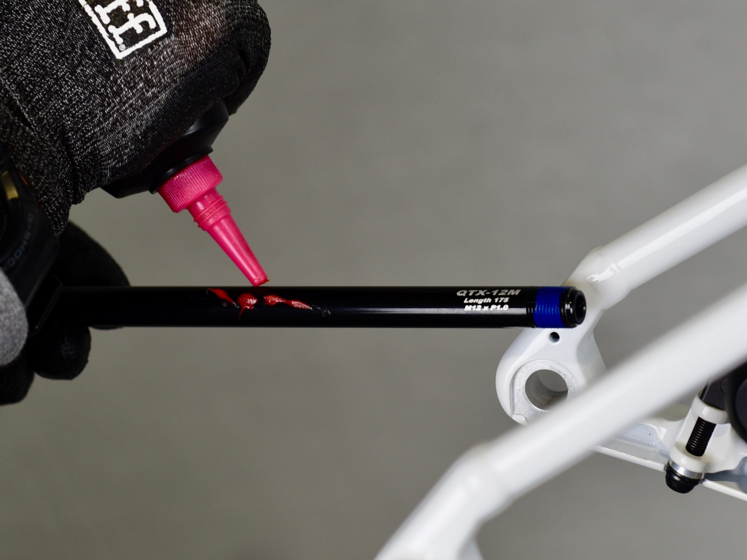
Grease rear wheel axle.
STEP 54
STEP 54
Install rear wheel axle.
STEP 55
STEP 55
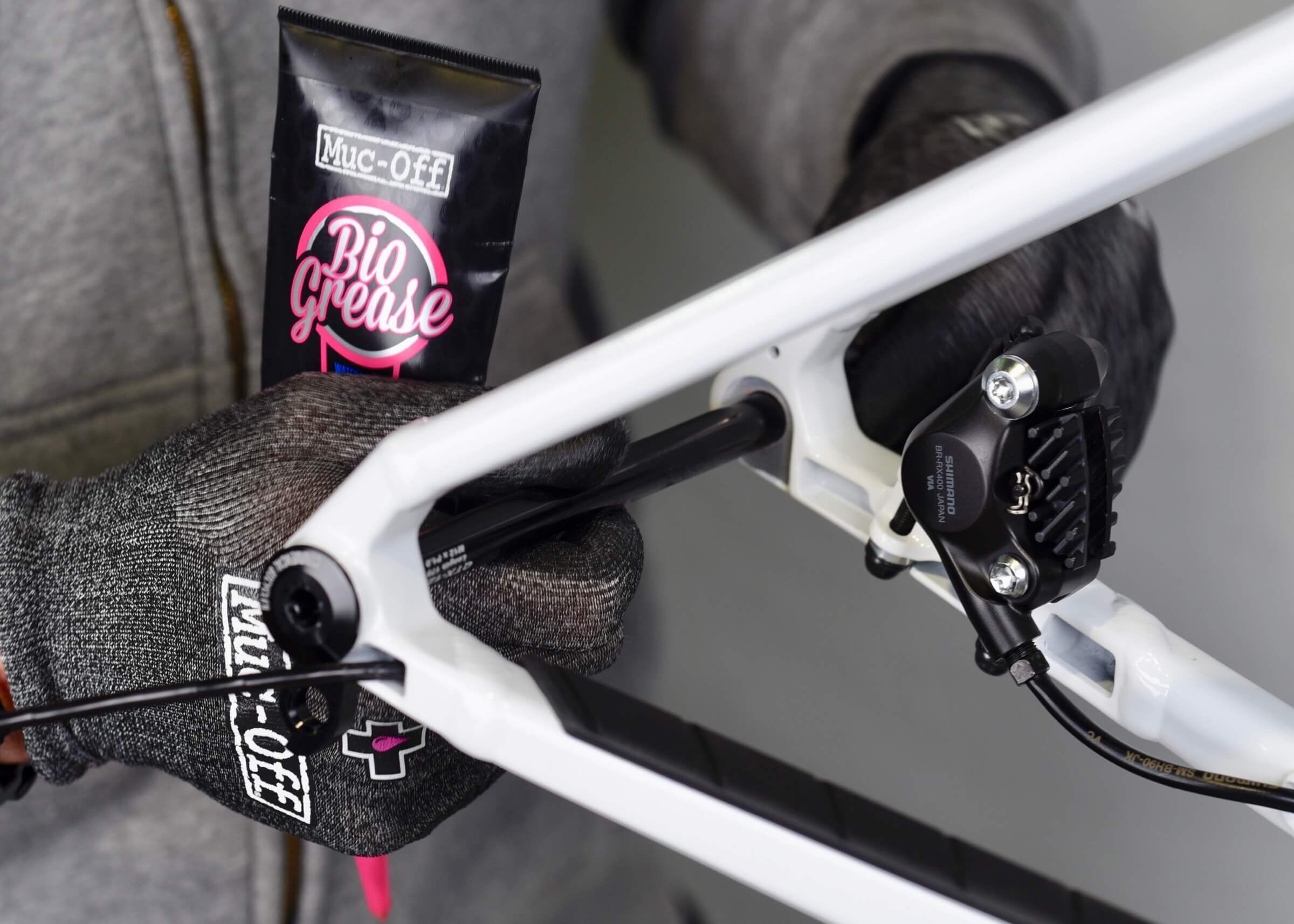
Grease front wheel axle and install it.
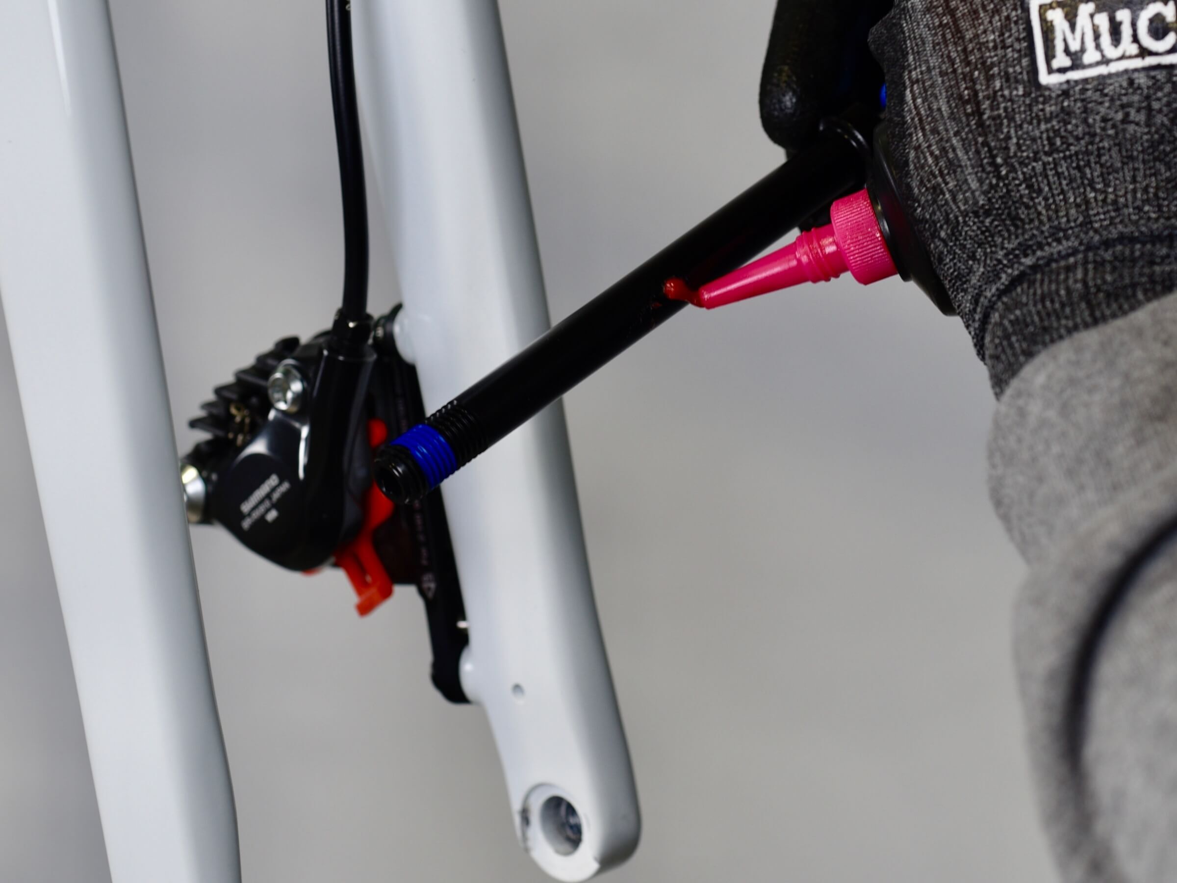
STEP 56
STEP 56
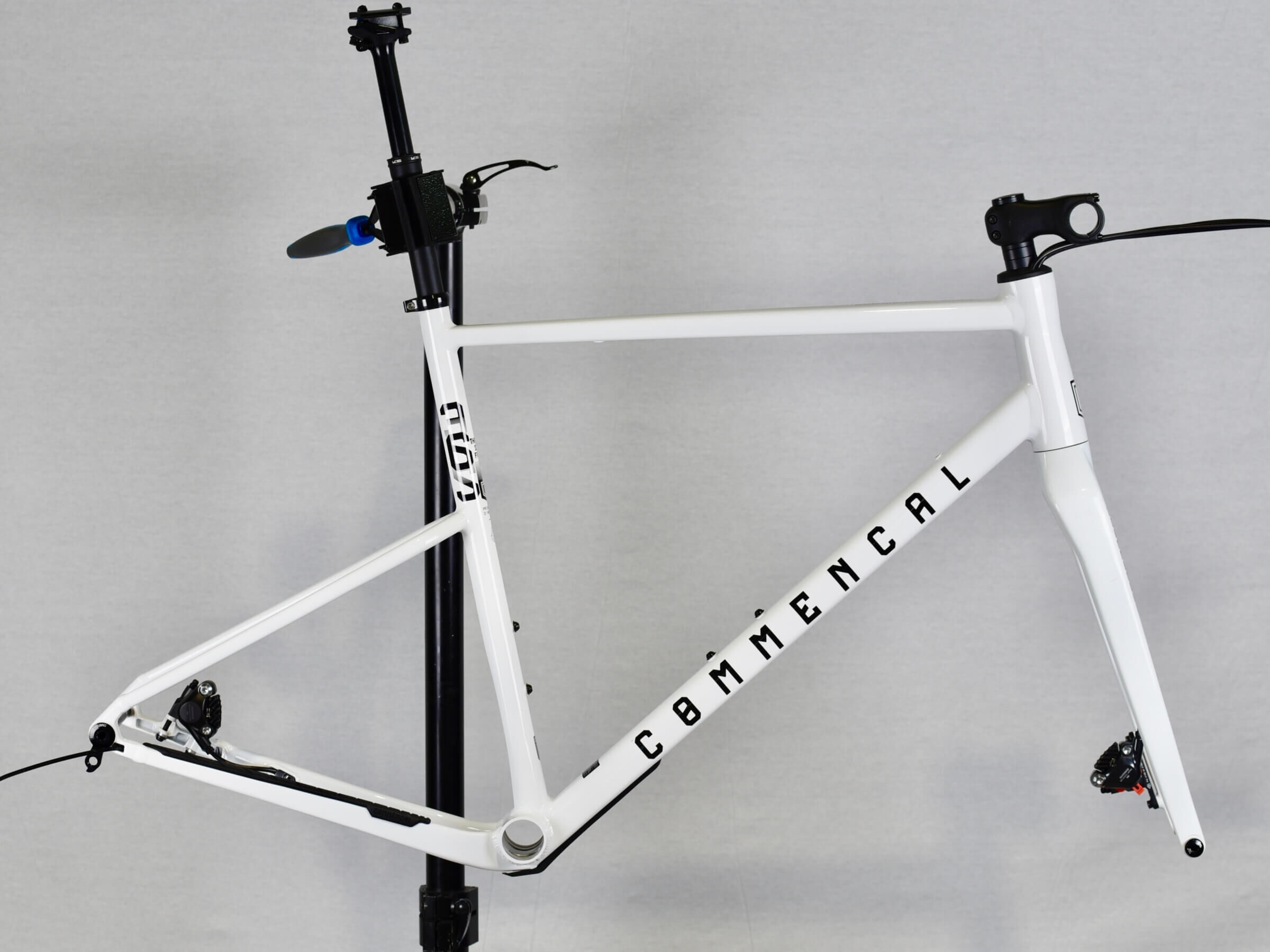
Your 365 frame is now ready for next step of the build, with every housing routed, headset, fork and stem installed.
Make sure to follow assembly and torque instructions, from the different brand parts.